
Datasheet


MSP430F47x3, MSP430F47x4
MIXED SIGNAL MICROCONTROLLER
SLAS545C − MAY 2007 − REVISED MARCH 2011
40
POST OFFICE BOX 655303 • DALLAS, TEXAS 75265
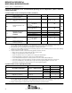
electrical characteristics over recommended operating free-air temperature (unless otherwise
noted) (continued)
Comparator_A (see Note 1)
PARAMETER TEST CONDITIONS V
CC
MIN TYP MAX UNIT
I
CAON 1 CARSEL 0 CAREF 0
2.2 V 25 40
A
I
(CC)
CAON = 1, CARSEL = 0, CAREF = 0
3 V 45 60
μA
I
CAON = 1, CARSEL = 0, CAREF =
1/2/3
2.2 V 30 50
A
I
(Refladder/RefDiode)
1/2/3,
No load at P1.6/CA0 and P1.7/CA1
3 V 45 80
μA
V
(Ref025)
Voltage @ 0.25 V
CC
node
V
CC
PCA0 = 1, CARSEL = 1, CAREF = 1,
No load at P1.6/CA0 and P1.7/CA1
2.2 V/3 V 0.23 0.24 0.25
V
(Ref050)
Voltage @ 0.5 V
CC
node
V
CC
PCA0 = 1, CARSEL = 1, CAREF = 2,
No load at P1.6/CA0 and P1.7/CA1
2.2 V/3 V 0.47 0.48 0.5
V
See Fi
g
ure 17 and
PCA0 = 1, CARSEL = 1, CAREF = 3,
No load at P1 6/CA0 and P1 7/CA1
2.2 V 390 480 540
mV
V
(RefVT)
See
Figure
17
and
Figure 18
No load at P1.6/CA0 and P1.7/CA1,
T
A
=
85°C
3 V 400 490 550
mV
V
IC
Common-mode input
voltage range
CAON = 1 2.2 V/3 V 0 V
CC
−1 V
V
p
−V
S
Offset voltage See Note 2 2.2 V/3 V −30 30 mV
V
hys
Input hysteresis CAON = 1 2.2 V/3 V 0 0.7 1.4 mV
T
A
= 25°C,
2.2 V 80 165 300
ns
t see Note 3
T
A
=
25 C
,
Overdrive 10 mV, without filter: CAF = 0
3 V 70 120 240
ns
t
(response
LH
and
HL)
, see Note 3
T
A
= 25°C
2.2 V 1.4 1.9 2.8
s
T
A
=
25 C
Overdrive 10 mV, with filter: CAF = 1
3 V 0.9 1.5 2.2
μs
NOTES: 1. The leakage current for the Comparator_A terminals is identical to I
lkg(Px.x)
specification.
2. The input offset voltage can be cancelled by using the CAEX bit to invert the Comparator_A inputs on successive measurements.
The two successive measurements are then summed together.
3. The response time is measured at P1.6/CA0 with an input voltage step and the Comparator_A already enabled (CAON = 1). If CAON
is set at the same time, a settling time of up to 300 ns is added to the response time.