
Datasheet


MSP430F471x3, MSP430F471x6, MSP430F471x7
MIXED SIGNAL MICROCONTROLLER
SLAS626C -- OCTOBER 2008 -- REVISED MARCH 2011
43
POST OFFICE BOX 655303 DALLAS, TEXAS 75265
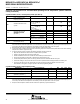
electrical characteristics over recommended operating free-air temperature (unless otherwise
noted) (continued)
crystal oscillator, XT2 oscillator (see Note 5)
PARAMETER TEST CONDITIONS V
CC
MIN TYP MAX UNIT
f
XT2,0
XT2 oscillator crystal frequency,
mode 0
XT2Sx = 0 1.8 V to 3.6 V 0.4 1 MHz
f
XT2,1
XT2 oscillator crystal frequency,
mode 1
XT2Sx = 1 1.8 V to 3.6 V 1 4 MHz
X
T
2
i
l
l
t
t
l
f
1.8 V to 3.6 V 2 10 MHz
f
X
T2
,
2
XT2 oscillator crystal frequency,
m
o
d
e
2
XT2Sx = 2
2.2 V to 3.6 V 2 12 MHz
f
X
T
2
,
2
mo
d
e
2
X
T
2
S
x
2
3.0 V to 3.6 V 2 16 MHz
X
T
2
i
l
l
t
l
i
l
l
1.8 V to 3.6 V 0.4 10 MHz
f
X
T2
,
lo
g
ic
XT2 oscillator logic level square
w
a
v
e
i
n
p
u
t
f
r
e
q
u
e
n
c
y
XT2Sx = 3
2.2 V to 3.6 V 0.4 12 MHz
f
X
T
2
,
l
o
g
i
c
wave
i
npu
t
f
requency
X
T
2
S
x
3
3.0 V to 3.6 V 0.4 16 MHz
XT2Sx = 0,
f
XT2
=1MHz,C
L,eff
=15pF
2700 Ω
OA
XT2
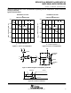
Oscillation allowance for HF
crystals (see Figure 16)
XT2Sx = 1
f
XT2
=4MHz,C
L,eff
=15pF
800 Ω
c
r
y
s
t
a
l
s
(
s
e
e
F
i
g
u
r
e
1
6
)
XT2Sx = 2
f
XT2
=16MHz,C
L,eff
=15pF
300 Ω
C
L,eff
Integrated effective load
capacitance (see Note 1)
(see Note 2) 1 pF
D
u
t
y
c
y
c
l
e
Measured at P1.5/TACLK/ACLK,
f
XT2
=10MHz
2.2 V/3 V 40 50 60 %
Duty cycle
Measured at P1.5/TACLK/ACLK,
f
XT2
=16MHz
2.2 V/3 V 40 50 60 %
f
Fault,XT2
Oscillator fault frequency
(see Note 4)
XT2Sx = 3 (see Notes 3) 2.2 V/3 V 30 300 kHz
NOTES: 1. Includes parasitic bond and package capacitance (approximately 2pF per pin).
Since the PCB adds additional capacitance it is recommended to verify the correct load by measuring the frequency. For a correct
setup the effective load capacitance should always match the specification of the used crystal.
2. Requires external capacitors at both terminals. Values are specified by crystal manufacturers.
3. Measured with logic level input frequency but also applies to operation with crystals.
4. Frequencies below the MIN specification will set the fault flag, frequencies above the MAX specification will not set the fault flag.
Frequencies in between might set the flag.
5. To improve EMI on the XT2 oscillator the following guidelines should be observed.
-- Keep the trace between the device and the crystal as short as possible.
-- Design a good ground plane around the oscillator pins.
-- Prevent crosstalk from other clock or data lines into oscillator pins XT2IN and XT2OUT.
-- Avoid running PCB traces underneath or adjacent to the XT2IN and XT2OUT pins.
-- Use assembly materials and praxis to avoid any parasitic load on the oscillator XT2IN and XT2OUT pins.
-- If conformal coating is used, ensure that it does not induce capacitive/resistive leakage between the oscillator pins.