
Datasheet


MSP430F471x3, MSP430F471x6, MSP430F471x7
MIXED SIGNAL MICROCONTROLLER
SLAS626C -- OCTOBER 2008 -- REVISED MARCH 2011
31
POST OFFICE BOX 655303 DALLAS, TEXAS 75265
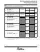
electrical characteristics over recommended operating free-air temperature (unless otherwise
noted)
supply c urrent into AV
CC
+DV
CC
excluding external current
PARAMETER TEST CONDITIONS V
CC
MIN TYP MAX UNIT
I
Active mode, (see Note 1)
f
(MCLK)
=f
(SMCLK)
=1MHz,
f
3
2
7
6
8
H
z
T
4
0
C
t
o
8
5
C
2.2 V 350 400
A
I
(AM)
(
)
(
)
f
(ACLK)
= 32768 Hz
XTS = 0, SELM = (0,1)
(Program executes from flash)
T
A
=--40Cto85C
3V 500 560
A
I
Low-
p
ower mode,
(
LPM0
)
T
4
0
C
t
o
8
5
C
2.2 V 45 70
A
I
(LPM0)
L
o
w
p
o
w
e
r
m
o
d
e
,
(
L
P
M
0
)
(see Notes 1, 4)
T
A
=--40Cto85C
3V 75 110
A
I
Low-power mode, (LPM2),
f
(
M
C
L
K
)
f
(
S
M
C
L
K
)
0
M
H
z
T
4
0
C
t
o
8
5
C
2.2 V 11 14
A
I
(LPM2)
f
(MCLK) =
f
(SMCLK) = 0 MHz,
f(ACLK) = 32768 Hz, SCG0 = 0 (see Notes 2, 4)
T
A
=--40Cto85C
3V 17 22
A
L
o
w
p
o
w
e
r
m
o
d
e
(
L
P
M
3
)
T
A
=--40C 0.7 2.0
Low-power mode, (LPM3)
f
(
M
C
L
K
)
=
f
(
S
M
C
L
K
)
=
0
M
H
z
,
T
A
=25C
2
2
V
0.8 2.0
A
f
(MCL
K
)
=
f
(SMCL
K
)
=
0
M
H
z
,
f
(
A
CL
K
)
= 32768 Hz, SCG0 = 1
T
A
=60C
2.2
V
2.0 3.5
A
I
f
(
A
C
L
K
)
3
2
7
6
8
H
z
,
S
C
G
0
1
Basic Timer1 and RTC enabled , ACLK selected
L
C
D
A
e
n
a
b
l
e
d
L
C
D
C
P
E
N
0
:
T
A
=85C 5.0 9.5
I
(LPM3)
LCD
_
A
enabled, LCDCPEN = 0:
(
s
t
a
t
i
c
m
o
d
e
,
f
L
C
D
=
f
(
A
C
L
K
)
/
3
2
)
T
A
=--40C 1.1 3.0
(
s
t
a
t
i
c
m
o
d
e
,
f
LCD
=
f
(
A
CL
K
)
/
3
2
)
(see Notes 2, 3, and 4)
T
A
=25C
3
V
1.2 3.0
A
(
s
e
e
o
t
e
s
,
3
,
a
d
)
T
A
=60C
3
V
2.5 4.0
A
T
A
=85C 6.0 10.0
L
o
w
p
o
w
e
r
m
o
d
e
(
L
P
M
3
)
T
A
=--40C 3.5 5.5
Low-power mode, (LPM3)
f
(
M
C
L
K
)
=
f
(
S
M
C
L
K
)
=
0
M
H
z
,
T
A
=25C
2
2
V
3.5 5.5
A
f
(MCL
K
)
=
f
(SMCL
K
)
=
0
M
H
z
,
f
(
A
CL
K
)
= 32768 Hz, SCG0 = 1
T
A
=60C
2.2
V
5.5 7.0
A
I
f
(
A
C
L
K
)
3
2
7
6
8
H
z
,
S
C
G
0
1
Basic Timer1 and RTC enabled , ACLK selected
L
C
D
A
e
n
a
b
l
e
d
L
C
D
C
P
E
N
0
:
T
A
=85C 11.0 17.0
I
(LPM3)
LCD
_
A
enabled, LCDCPEN = 0:
(
4
-
m
u
x
m
o
d
e
,
f
L
C
D
=
f
(
A
C
L
K
)
/
3
2
)
T
A
=--40C 4.0 6.5
(
4
-
m
u
x
m
o
d
e
,
f
LCD
=
f
(
A
CL
K
)
/
3
2
)
(see Notes 2, 3, and 4)
T
A
=25C
3
V
4.0 6.5
A
(
s
e
e
o
t
e
s
,
3
,
a
d
)
T
A
=60C
3
V
6.0 8.0
A
T
A
=85C 13.0 20.0
T
A
=--40C 0.1 1.0
T
A
=25C
2
2
V
0.2 1.0
A
T
A
=60C
2.2
V
1.0 2.5
A
I
Low-power mode, (LPM4)
f
0
M
H
z
f
0
M
H
z
T
A
=85C 4.5 8.5
I
(LPM4)
f
(MCLK)
=0MHz,
f
(SMCLK)
=0MHz,
f
(
A
C
L
K
)
=
0
H
z
,
S
C
G
0
=
1
(
s
e
e
N
o
t
e
s
2
a
n
d
4
)
T
A
=--40C 0.1 2.0
f
(
A
CL
K
)
=
0
H
z
,
S
C
G
0
=
1
(
s
e
e
N
o
t
e
s
2
a
n
d
4
)
T
A
=25C
3
V
0.2 2.0
A
T
A
=60C
3
V
1.5 3.0
A
T
A
=85C 5.0 9.0
NOTES: 1. Timer_Aisclockedbyf
(DCOCLK)
=f
(DCO)
= 1 MHz. All inputs are tied to 0 V or to V
CC
. Outputs do not source or sink any current.
2. All i nputs are tied to 0 V or to V
CC
. Outputs do not source or sink any current.
3. The LPM3 currents are characterized with a Micro Crystal CC4V --T1A (9 pF) crystal and OSCCAPx = 01h.
4. Current for brownout included.