
Datasheet


MSP430F42x0
MIXED SIGNAL MICROCONTROLLER
SLAS455D − MARCH 2005 − REVISED APRIL 2007
20
POST OFFICE BOX 655303 • DALLAS, TEXAS 75265
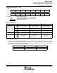
electrical characteristics over recommended operating free-air temperature (unless otherwise
noted) (continued)
outputs − Ports P1, P2, P5, and P6
PARAMETER TEST CONDITIONS MIN TYP MAX UNIT
I
OH(max)
= −1.5 mA, V
CC
= 2.2 V, See Note 1 V
CC
−0.25 V
CC
V
High level output voltage
I
OH(max)
= −6 mA, V
CC
= 2.2 V, See Note 2 V
CC
−0.6 V
CC
V
V
OH
High-level output voltage
I
OH(max)
= −1.5 mA, V
CC
= 3 V, See Note 1 V
CC
−0.25 V
CC
V
I
OH(max)
= −6 mA, V
CC
= 3 V, See Note 2 V
CC
−0.6 V
CC
I
OL(max)
= 1.5 mA, V
CC
= 2.2 V, See Note 1 V
SS
V
SS
+0.25
V
Low level output voltage
I
OL(max)
= 6 mA, V
CC
= 2.2 V, See Note 2 V
SS
V
SS
+0.6
V
V
OL
Low-level output voltage
I
OL(max)
= 1.5 mA, V
CC
= 3 V, See Note 1 V
SS
V
SS
+0.25
V
I
OL(max)
= 6 mA, V
CC
= 3 V, See Note 2 V
SS
V
SS
+0.6
NOTES: 1. The maximum total current, I
OH(max)
and I
OL(max),
for all outputs combined, should not exceed ±12 mA to satisfy the maximum
specified voltage drop.
2. The maximum total current, I
OH(max)
and I
OL(max),
for all outputs combined, should not exceed ±48 mA to satisfy the maximum
specified voltage drop.
output frequency
PARAMETER TEST CONDITIONS MIN TYP MAX UNIT
f
(Px.y)
(x = 1, 2, 5, 6; 0 ≤ y ≤ 7)
C
L
= 20 pF,
I
L
= ±1.5 mA
V
CC
= 2.2 V / 3 V DC f
System
MHz
f
(MCLK)
P1.1/TA0/MCLK C
L
= 20 pF f
System
MHz
P1.1/TA0/MCLK
,
f
(MCLK)
= f
(XT1)
40% 60%
t
(Xdc)
Duty cycle of output frequency
P1
.
1/TA0/MCLK
,
C
L
= 20 pF,
V
CC
= 2.2 V / 3 V
f
(MCLK)
= f
(DCOCLK)
50%−
15 ns
50%
50%+
15 ns