
Datasheet


MSP430F20x3
MSP430F20x2
MSP430F20x1
SLAS491I –AUGUST 2005–REVISED DECEMBER 2012
www.ti.com
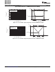
Schmitt-Trigger Inputs (Ports P1 and P2)
over recommended ranges of supply voltage and operating free-air temperature (unless otherwise noted)
PARAMETER TEST CONDITIONS V
CC
MIN TYP MAX UNIT
0.45 V
CC
0.75 V
CC
V
IT+
Positive-going input threshold voltage 2.2 V 1.00 1.65 V
3 V 1.35 2.25
0.25 V
CC
0.55 V
CC
V
IT-
Negative-going input threshold voltage 2.2 V 0.55 1.20 V
3 V 0.75 1.65
2.2 V 0.2 1.0
V
hys
Input voltage hysteresis (V
IT+
- V
IT-
) V
3 V 0.3 1.0
For pullup: V
IN
= V
SS
,
R
Pull
Pullup/pulldown resistor 20 35 50 kΩ
For pulldown: V
IN
= V
CC
C
I
Input capacitance V
IN
= V
SS
or V
CC
5 pF
Inputs (Ports P1 and P2)
over recommended ranges of supply voltage and operating free-air temperature (unless otherwise noted)
PARAMETER TEST CONDITIONS V
CC
MIN TYP MAX UNIT
Port P1, P2: P1.x to P2.x, External trigger pulse
t
(int)
External interrupt timing 2.2 V, 3 V 20 ns
width to set interrupt flag
(1)
(1) An external signal sets the interrupt flag every time the minimum interrupt pulse width t
(int)
is met. It may be set even with trigger signals
shorter than t
(int)
.
Leakage Current (Ports P1 and P2)
over recommended ranges of supply voltage and operating free-air temperature (unless otherwise noted)
PARAMETER TEST CONDITIONS V
CC
MIN MAX UNIT
I
lkg(Px.y)
High-impedance leakage current
(1) (2)
2.2 V, 3 V ±50 nA
(1) The leakage current is measured with V
SS
or V
CC
applied to the corresponding pins, unless otherwise noted.
(2) The leakage of the digital port pins is measured individually. The port pin is selected for input and the pullup or pulldown resistor is
disabled.
24 Submit Documentation Feedback Copyright © 2005–2012, Texas Instruments Incorporated