
Datasheet


SLAS361D − JANUARY 2002 − REVISED AUGUST 2004
18
POST OFFICE BOX 655303 • DALLAS, TEXAS 75265
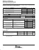
electrical characteristics over recommended ranges of supply voltage and operating free-air
temperature (unless otherwise noted) (continued)
Schmitt-trigger inputs Port P1 to Port P3; P1.0 to P1.7, P2.0 to P2.5, P3.0 to P3.7
PARAMETER TEST CONDITIONS MIN TYP MAX UNIT
V
CC
= 2.2 V 1.1 1.5
V
IT+
Positive-going input threshold voltage
V
CC
= 3 V 1.5 1.9
V
V
CC
= 2.2 V 0.4 0.9
V
IT−
Negative-going input threshold voltage
V
CC
= 3 V 0.9 1.3
V
V
CC
= 2.2 V 0.3 1.1
V
hys
Input voltage hysteresis, (V
IT+
− V
IT−
)
V
CC
= 3 V 0.5 1
V
standard inputs − RST/NMI, TEST; JTAG: TCK, TMS, TDI/TCLK
PARAMETER TEST CONDITIONS MIN TYP MAX UNIT
V
IL
Low-level input voltage V
SS
V
SS
+0.6 V
V
IH
High-level input voltage
V
CC
= 2.2 V / 3 V
0.8×V
CC
V
CC
V
inputs Px.x, TAx
PARAMETER TEST CONDITIONS V
CC
MIN TYP MAX UNIT
2.2 V/3 V 1.5 cycle
t
(int)
External interrupt timing
Port P1, P2: P1.x to P2.x, External trigger signal
2.2 V 62
(int)
for the interrupt flag, (see Note 1)
3 V 50
ns
2.2 V 62
t
(cap)
Timer_A, capture timing TA0, TA1, TA2
3 V 50
ns
Timer_A clock frequency
2.2 V 8
f
(TAext)
Timer_A clock frequency
externally applied to pin
TACLK, INCLK
t
(H)
= t
(L)
3 V 10
MHz
2.2 V 8
f
(TAint)
Timer_A clock frequency SMCLK or ACLK signal selected
3 V 10
MHz
NOTES: 1. The external signal sets the interrupt flag every time the minimum t
(int)
cycle and time parameters are met. It may be set even with
trigger signals shorter than t
(int)
. Both the cycle and timing specifications must be met to ensure the flag is set. t
(int)
is measured in
MCLK cycles.
leakage current
PARAMETER TEST CONDITIONS V
CC
MIN TYP MAX UNIT
Port P1: P1.x, 0 ≤ ×≤ 7
(see Notes 1 and 2)
2.2 V/3 V ±50
I
lkg(Px.x)
High-impedance leakage current
Port P2: P2.x, 0 ≤ ×≤ 5
(see Notes 1 and 2)
2.2 V/3 V ±50
nA
NOTES: 1. The leakage current is measured with V
SS
or V
CC
applied to the corresponding pin(s), unless otherwise noted.
2. The leakage of the digital port pins is measured individually. The port pin must be selected for input and there must be no optional
pullup or pulldown resistor.