
Datasheet


MC1489, MC1489A, SN55189, SN55189A, SN75189, SN75189A
QUADRUPLE LINE RECEIVERS
SLLS095D – SEPTEMBER 1973 – REVISED OCTOBER 1998
8
POST OFFICE BOX 655303 • DALLAS, TEXAS 75265
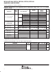
TYPICAL CHARACTERISTICS
†
Figure 7
INPUT THRESHOLD VOLTAGE
vs
FREE-AIR TEMPERATURE
2.2
2
1.8
1.6
1.4
1.2
1
0.8
0.6
1251007550250–25–50–75
0.4
150
2.4
T
A
– Free-Air Temperature – °C
–100
’89 V
IT+
’89A V
IT–
’89 V
IT–
’89A V
IT+
– Input Threshold Voltage – V
V
IT
Figure 8
– Input Threshold Voltage – V
INPUT THRESHOLD VOLTAGE
vs
SUPPLY VOLTAGE
’89A V
IT–
’89 V
IT+
’89 V
IT–
’89A V
IT+
1.8
1.6
1.4
1.2
1
0.8
0.6
0.4
0.2
9876543
0
10
2
V
CC
– Supply Voltage – V
2
V
IT
Figure 9
Amplitude – V
SN75189
NOISE REJECTION
T
A
= 25°C
V
CC
= 5 V
4000100040010040
5
4
3
2
1
0
10000
6
t
w
– Pulse Duration – ns
10
C
C
= 500 pF
C
C
= 10 pF
C
C
= 100 pF
C
C
= 300 pF
See Note A
NOTE A: Maximum amplitude of a positive-going pulse that,
starting from 0 V, will not cause a change in the
output level.
Figure 10
Amplitude – V
SN75189A
NOISE REJECTION
C
C
= 300 pF
10
t
w
– Pulse Duration – ns
6
10000
0
1
2
3
4
5
40 100 400 1000 4000
C
C
= 500 pF
C
C
= 12 pF
C
C
= 100 pF
V
CC
= 5 V
T
A
= 25°C
See Note A
NOTE A: Maximum amplitude of a positive-going pulse that,
starting from 0 V, will not cause a change in the
output level.
†
Data for free-air temperatures below 0°C and above 70°C are applicable to SN55189 and SN55189A circuits only.