
Datasheet


MAX3318E
www.ti.com
SLLS741A –JUNE 2006–REVISED OCTOBER 2013
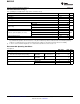
Supply Current Section Electrical Characteristics
V
CC
= 2.25 V to 3 V, C1–C4 = 0.1 μF, T
A
= T
MIN
to T
MAX
(unless otherwise noted)
PARAMETER TEST CONDITIONS MIN TYP
(1)
MAX UNIT
DC Characteristics (V
CC
= 2.5 V, T
A
= 25°C)
Auto-power-down plus supply current FORCEON = GND, FORCEOFF = V
CC
, All RIN and DIN idle 1 10 μA
Auto-power-down supply current FORCEOFF = GND 1 10 μA
Supply current FORCEON = FORCEOFF = V
CC
, No load 0.3 2 mA
(1) Typical values are at V
CC
= 2.5 V, T
A
= 25°C.
ESD Protection
PARAMETER TEST CONDITIONS TYP UNIT
HBM ±15
RIN, DOUT IEC 61000-4-2 Air-Gap Discharge method ±15 kV
IEC 61000-4-2 Contact Discharge method ±8
Driver Section Electrical Characteristics
over recommended ranges of supply voltage and operating free-air temperature,
V
CC
= 2.25 V to 3 V, C1–C4 = 0.1 μF, T
A
= T
MIN
to T
MAX
(unless otherwise noted) (see Figure 4)
PARAMETER TEST CONDITIONS MIN TYP
(1)
MAX UNIT
Driver input hysteresis 0.3 V
Input leakage current FORCEON, DIN, FORCEOFF ±0.01 ±1 μA
Output voltage swing All driver outputs loaded with 3 kΩ to ground ±3.7 ±4 V
Output resistance V
CC
= 0, Driver output = ±2 V 300 10M Ω
Output short-circuit current
(2)
±25 ±60 mA
Output leakage current V
CC
= 0 or 2.25 V to 3 V, V
OUT
= ± 12 V, Drivers disabled ±25 μA
(1) Typical values are at V
CC
= 2.5 V, T
A
= 25°C.
(2) Short-circuit durations should be controlled to prevent exceeding the device absolute power dissipation ratings, and not more than one
output should be shorted at a time.
Driver Section Switching Characteristics
over recommended ranges of supply voltage and operating free-air temperature,
V
CC
= 2.25 V to 3 V, C1–C4 = 0.1 μF, T
A
= T
MIN
to T
MAX
(unless otherwise noted) (see Figure 1)
PARAMETER TEST CONDITIONS MIN TYP
(1)
MAX UNIT
Maximum data rate R
L
= 3 kΩ, C
L
= 1000 pF, One transmitter switching 460 kbps
|t
PHL
– t
PLH
| Driver skew
(2)
100 ns
V
CC
= 2.5 V, T
A
= 25°C, R
L
= 3 kΩ to 7 kΩ,
Transition-region slew rate Measured from 3 V to –3 V or –3 V to 3 V, 4 30 V/μs
C
L
= 150 pF to 2500 pF
(1) Typical values are at V
CC
= 2.5 V, T
A
= 25°C.
(2) Pulse skew is defined as |t
PLH
– t
PHL
| of each channel of the same device.
Copyright © 2006–2013, Texas Instruments Incorporated Submit Documentation Feedback 5
Product Folder Links: MAX3318E