
Datasheet


MAX3223E
www.ti.com
.......................................................................................................................................... SLLS707A –JANUARY 2006–REVISED SEPTEMBER 2009
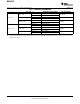
RECOMMENDED OPERATING CONDITIONS
(1)
See Figure 6
MIN NOM MAX UNIT
V
CC
= 3.3 V 3 3.3 3.6
Supply voltage V
V
CC
= 5 V 4.5 5 5.5
V
CC
= 3.3 V 2
Driver and control
V
IH
DIN, EN, FORCEOFF, FORCEON V
high-level input voltage
V
CC
= 5 V 2.4
Driver and control
V
IL
DIN, EN, FORCEOFF, FORCEON 0.8 V
low-level input voltage
Driver and control input voltage DIN, EN, FORCEOFF, FORCEON 0 5.5 V
V
I
Receiver input voltage –25 25 V
MAX3223EC 0 70
T
A
Operating free-air temperature °C
MAX3223EI –40 85
(1) Test conditions are C1–C4 = 0.1 μF at V
CC
= 3.3 V ± 0.3 V; C1 = 0.047 μF, C2–C4 = 0.33 μF at V
CC
= 5 V ± 0.5 V.
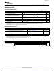
ELECTRICAL CHARACTERISTICS
(1)
over recommended ranges of supply voltage and operating free-air temperature (unless otherwise noted) (see Figure 5)
PARAMETER TEST CONDITIONS MIN TYP
(2)
MAX UNIT
Input leakage EN, FORCEOFF,
I
I
±0.01 ±1 μA
current FORCEON
V
CC
= 3.3 V or 5 V, T
A
= 25°C,
Auto-powerdown disabled 0.3 1 mA
No load, FORCEOFF and FORCEON at V
CC
Powered off No load, FORCEOFF at GND 1 10
I
CC
Supply current
No load, FORCEOFF at V
CC
, FORCEON at
μA
Auto-powerdown enabled GND, 1 10
All RIN are open or grounded
(1) Test conditions are C1–C4 = 0.1 μF at V
CC
= 3.3 V ± 0.3 V; C1 = 0.047 μF, C2–C4 = 0.33 μF at V
CC
= 5 V ± 0.5 V.
(2) All typical values are at V
CC
= 3.3 V or V
CC
= 5 V, and T
A
= 25°C.
Copyright © 2006–2009, Texas Instruments Incorporated Submit Documentation Feedback 5
Product Folder Link(s): MAX3223E