
Datasheet


±
SLLS408G − JANUARY 2000 − REVISED MARCH 2004
2
POST OFFICE BOX 655303 • DALLAS, TEXAS 75265
description/ordering information (continued)
The MAX3222 can be placed in the power-down mode by setting PWRDOWN low, which draws only 1 µA from
the power supply. When the device is powered down, the receivers remain active while the drivers are placed
in the high-impedance state. Also, during power down, the onboard charge pump is disabled; V+ is lowered to
V
CC
, and V− is raised toward GND. Receiver outputs also can be placed in the high-impedance state by setting
EN
high.
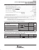
Function Tables
EACH DRIVER
INPUTS
OUTPUT
DIN
PWRDOWN
OUTPUT
DOUT
X L Z
L HH
H H L
H = high level, L = low level, X = irrelevant,
Z = high impedance
EACH RECEIVER
INPUTS
OUTPUT
RIN
EN
OUTPUT
ROUT
L L H
H LL
X HZ
Open L H
H = high level, L = low level, X = irrelevant,
Z = high impedance (off), Open = input
disconnected or connected driver off
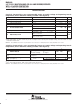
logic diagram (positive logic)
DIN2
DOUT2
12 8
Powerdown
RIN1
16
20
15
PWRDOWN
ROUT1
DIN1
DOUT1
13 17
RIN2
910
ROUT2
1
EN