
Datasheet


Table Of Contents
- Features
- Applications
- Description
- Absolute Maximum Ratings
- Recommended Operating Conditions
- Electrical Characteristics
- Driver Section
- Electrical Characteristics
- Switching Characteristics
- ESD Protection
- Receiver Section
- Electrical Characteristics
- Switching Characteristics
- ESD Protection
- Auto-Powerdown Section
- Electrical Characteristics
- Switching Characteristics
- Parameter Measurement Information
- Application Information
- Revision History
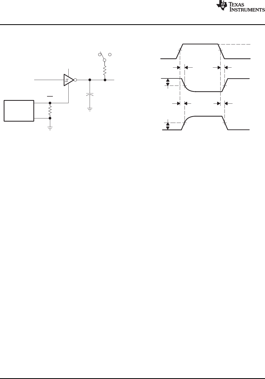
TEST CIRCUIT VOLTAGE WAVEFORMS
50 Ω
Generator
(see Note B)
3 V or 0 V
Output
V
OL
V
OH
t
PZH
(S1 at GND)
3 V
0 V
0.3 V
Output
Input
0.3 V
3 V or 0 V
FORCEON
EN
1.5 V 1.5 V
50%
t
PHZ
(S1 at GND)
t
PLZ
(S1 at V
CC
)
50%
t
PZL
(S1 at V
CC
)
R
L
S1
V
CC
GND
C
L
(see Note A)
Output
MAX3221
SLLS348N –JUNE 1999–REVISED JANUARY 2014
www.ti.com
Parameter Measurement Information (continued)
A. C
L
includes probe and jig capacitance.
B. The pulse generator has the following characteristics: Z
O
= 50 Ω, 50% duty cycle, t
r
≤ 10 ns, t
f
≤ 10 ns.
C. t
PLZ
and t
PHZ
are the same as t
dis
.
D. t
PZL
and t
PZH
are the same as t
en
.
Figure 4. Receiver Enable and Disable Times
8 Submit Documentation Feedback Copyright © 1999–2014, Texas Instruments Incorporated
Product Folder Links :MAX3221