
Datasheet


LT1004-1.2, LT1004-2.5
MICROPOWER INTEGRATED VOLTAGE REFERENCES
SLVS022M − JANUARY 1989 − REVISED MAY 2008
4
POST OFFICE BOX 655303 • DALLAS, TEXAS 75265
absolute maximum ratings over operating free-air temperature range (unless otherwise noted)
†
Reverse current, I
R
30 mA. . . . . . . . . . . . . . . . . . . . . . . . . . . . . . . . . . . . . . . . . . . . . . . . . . . . . . . . . . . . . . . . . . . . . . .
Forward current, I
F
10 mA. . . . . . . . . . . . . . . . . . . . . . . . . . . . . . . . . . . . . . . . . . . . . . . . . . . . . . . . . . . . . . . . . . . . . . .
Package thermal impedance, θ
JA
(see Notes 1 and 2): D package 97°C/W. . . . . . . . . . . . . . . . . . . . . . . . . . . .
PW package 149°C/W. . . . . . . . . . . . . . . . . . . . . . . . .
Operating virtual junction temperature, T
J
150°C. . . . . . . . . . . . . . . . . . . . . . . . . . . . . . . . . . . . . . . . . . . . . . . . . . .
Lead temperature 1,6 mm (1/16 inch) from case for 10 seconds 260°C. . . . . . . . . . . . . . . . . . . . . . . . . . . . . . .
Storage temperature range, T
stg
−65°C to 150°C. . . . . . . . . . . . . . . . . . . . . . . . . . . . . . . . . . . . . . . . . . . . . . . . . . .
†
Stresses beyond those listed under “absolute maximum ratings” may cause permanent damage to the device. These are stress ratings only, and
functional operation of the device at these or any other conditions beyond those indicated under “recommended operating conditions” is not
implied. Exposure to absolute-maximum-rated conditions for extended periods may affect device reliability.
NOTES: 1. Maximum power dissipation is a function of T
J
(max), θ
JA
, and T
A
. The maximum allowable power dissipation at any allowable
ambient temperature is P
D
= (T
J
(max) − T
A
)/θ
JA
. Operating at the absolute maximum T
J
of 150°C can affect reliability.
2. The package thermal impedance is calculated in accordance with JESD 51-7.
recommended operating conditions
MIN MAX
UNIT
T
Operating free air temperature
LT1004C 0 70
°C
T
A
Operating free-air temperature
LT1004I −40 85
°C
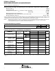
electrical characteristics at specified free-air temperature
PARAMETER
TEST
T
‡
LT1004-1.2 LT1004-2.5
UNIT
PARAMETER
TEST
CONDITIONS
T
A
‡
MIN TYP MAX MIN TYP MAX
UNIT
25°C 1.231 1.235 1.239 2.48 2.5 2.52
V
Z
Reference voltage I
Z
= 100 µA
Full
LT1004C 1.225 1.245 2.47 2.53
V
V
Z
Reference
voltage
I
Z
100
µA
Full
range
LT1004I 1.225 1.245 2.47 2.53
V
a
V
Average
temperature coefficient
I
Z
= 10 µA
25°C
20
ppm/°C
a
V
Z
temperature coefficient
of reference voltage
§
I
Z
= 20 µA
25°C
20
ppm/°C
I I (min) to 1 mA
25°C 1 1
∆V
Change in
reference voltage
I
Z
= I
Z
(min) to 1 mA
Full range 1.5 1.5
mV
∆V
Z
reference voltage
with
cu
rr
e
nt
I 1mAto20mA
25°C 10 10
mV
with
current
I
Z
= 1 mA to 20 mA
Full range 20 20
∆V
Z
/∆t
Long-term change
in reference voltage
I
Z
= 100 µA 25°C 20 20 ppm/khr
I
Z
(min)
Minimum
reference current
Full range 8 10 12 20 µA
z
Reference impedance
I 100 A
25°C 0.2 0.6 0.2 0.6
Ω
z
z
Reference impedance I
Z
= 100 µA
Full range 1.5 1.5
Ω
V
n
Broadband
noise voltage
I
Z
= 100 µA,
f = 10 Hz to 10 kHz
25°C 60 120 µV
‡
Full range is 0°C to 70°C for the LT1004C and −40°C to 85°C for the LT1004I.
§
The average temperature coefficient of reference voltage is defined as the total change in reference voltage divided by the specified temperature
range.