
Datasheet


0
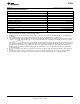
200 400 600 800
LOAD CURRENT (mA)
0
0.1
0.2
0.3
0.4
ESR (:)
STABLE REGION
LP3879
www.ti.com
SNVS396B –MAY 2006–REVISED APRIL 2013
Figure 19. Stable Region For Output Capacitor ESR
Important: The output capacitor must maintain its ESR within the stable region over the full operating
temperature range of the application to assure stability.
The output capacitor ESR forms a zero which is required to add phase lead near the loop gain crossover
frequency, typically in the range of 50kHz to 200 kHz. The ESR at lower frequencies is of no importance. Some
capacitor manufacturers list ESR at low frequencies only, and some give a formula for Dissipation Factor which
can be used to calculate a value for a term referred to as ESR. However, since the DF formula is usually at a
much lower frequency than the range listed above, it will give an unrealistically high value. If good quality X5R or
X7R ceramic capacitors are used, the actual ESR in the 50 kHz to 200 kHz range will not exceed 25 milli Ohms.
If these are used as output capacitors for the LP3879, the regulator stability requirements are satisfied.
It is important to remember that capacitor tolerance and variation with temperature must be taken into
consideration when selecting an output capacitor so that the minimum required amount of output capacitance is
provided over the full operating temperature range. (See Capacitor Characteristics section).
The output capacitor must be located not more than 0.5" from the output pin and returned to a clean analog
ground.
NOISE BYPASS CAPACITOR: The 10 nF capacitor on the Bypass pin significantly reduces noise on the
regulator output and is required for loop stability. However, the capacitor is connected directly to a high-
impedance circuit in the bandgap reference.
Because this circuit has only a few microamperes flowing in it, any significant loading on this node will cause a
change in the regulated output voltage. For this reason, DC leakage current through the noise bypass capacitor
must never exceed 100 nA, and should be kept as low as possible for best output voltage accuracy.
The types of capacitors best suited for the noise bypass capacitor are ceramic and film. High-quality ceramic
capacitors with either NPO or COG dielectric typically have very low leakage. 10 nF polypropolene and
polycarbonate film capacitors are available in small surface-mount packages and typically have extremely low
leakage current.
CAPACITOR CHARACTERISTICS
CERAMIC: The LP3879 was designed to work with ceramic capacitors on the output to take advantage of the
benefits they offer: for capacitance values in the 10 µF range, ceramics are the least expensive and also have
the lowest ESR values (which makes them best for eliminating high-frequency noise). The ESR of a typical 10 µF
ceramic capacitor is in the range of 5 mΩ to 10 mΩ, which meets the ESR limits required for stability by the
LP3879.
One disadvantage of ceramic capacitors is that their capacitance can vary with temperature. Many large value
ceramic capacitors (≥ 2.2 µF) are manufactured with the Z5U or Y5V temperature characteristic, which results in
the capacitance dropping by more than 50% as the temperature goes from 25°C to 85°C.
Another significant problem with Z5U and Y5V dielectric devices is that the capacitance drops severely with
applied voltage. A typical Z5U or Y5V capacitor can lose 60% of its rated capacitance with half of the rated
voltage applied to it.
Copyright © 2006–2013, Texas Instruments Incorporated Submit Documentation Feedback 9
Product Folder Links: LP3879