
Datasheet


LMV821-N, LMV822-N, LMV822-N-Q1
LMV824-N, LMV824-N-Q1
www.ti.com
SNOS032G –AUGUST 1999–REVISED NOVEMBER 2013
(5)
Notice that R
3
could also be calculated as 0.707 of R
a
or R
2.
The circuit was implemented and its cutoff frequency measured. The cutoff frequency measured at 2.92 kHz.
The circuit also showed good repeatability. Ten different LMV822 samples were placed in the circuit. The
corresponding change in the cutoff frequency was less than a percent.
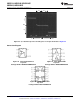
TRI-LEVEL VOLTAGE DETECTOR
The tri-level voltage detector of Figure 44 provides a type of window comparator function. It detects three
different input voltage ranges: Min-range, Mid-range, and Max-range. The output voltage (V
O
) is at V
CC
for the
Min-range. V
O
is clamped at GND for the Mid-range. For the Max-range, V
O
is at V
ee
. Figure 45 shows a V
O
vs.
V
I
oscilloscope photo per the circuit of Figure 44.
Its operation is as follows: V
I
deviating from GND, causes the diode bridge to absorb I
IN
to maintain a clamped
condition (V
O
= 0V). Eventually, I
IN
reaches the bias limit of the diode bridge. When this limit is reached, the
clamping effect stops and the op amp responds open loop. The design equation directly preceding Figure 45,
shows how to determine the clamping range. The equation solves for the input voltage band on each side GND.
The mid-range is twice this voltage band.
Figure 44. Tri-level Voltage Detector
Copyright © 1999–2013, Texas Instruments Incorporated Submit Documentation Feedback 21
Product Folder Links: LMV821-N LMV822-N LMV822-N-Q1 LMV824-N LMV824-N-Q1