
Datasheet


10
100 1k 10k
FREQUENCY (Hz)
-140
-120
-100
-80
-60
-40
-20
0
CMRR (dB)
V
S
= ±2.5V
V
CM
= 0V
V
IN
= 3V
PP
V
O
= -K (2a + 1) (V
1
- V
2
)
V
O
=
KR
2
R
2
(V
O2
- V
O1
)
= -K (V
O1
- V
O2
)
R
11
= V
1
- V
2
V
V
O1
- V
O2
= (2R
1
+
) I
R
11
R
11
= (2a + 1) V
R
11
= (2a + 1)
R
11
x
I
R
11
GIVEN: I
R
1
= I
R
11
LMV771, LMV772, LMV774
www.ti.com
SNOSA04F –MAY 2004–REVISED SEPTEMBER 2010
There are two stages in this amplifier. The last stage, output stage, is a differential amplifier. In an ideal case the
two amplifiers of the first stage, input stage, would be set up as buffers to isolate the inputs. However they
cannot be connected as followers because of real amplifier's mismatch. That is why there is a balancing resistor
between the two. The product of the two stages of gain will give the gain of the instrumentation amplifier. Ideally,
the CMRR should be infinite. However the output stage has a small non-zero common mode gain which results
from resistor mismatch.
In the input stage of the circuit, current is the same across all resistors. This is due to the high input impedance
and low input bias current of the LMV771. With the node equations we have:
(2)
By Ohm’s Law:
(3)
However:
(4)
So we have:
(5)
Now looking at the output of the instrumentation amplifier:
(6)
Substituting from Equation 5:
(7)
This shows the gain of the instrumentation amplifier to be:
−K(2a+1) (8)
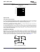
Typical values for this circuit can be obtained by setting: a = 12 and K= 4. This results in an overall gain of −100.
Figure 6 shows typical CMRR characteristics of this Instrumentation amplifier over frequency. Three LMV771
amplifiers are used along with 1% resistors to minimize resistor mismatch. Resistors used to build the circuit are:
R
1
= 21.6kΩ, R
11
= 1.8kΩ, R
2
= 2.5kΩ with K = 40 and a = 12. This results in an overall gain of −1000, −K(2a+1)
= −1000.
Figure 6. CMRR vs. Frequency
Copyright © 2004–2010, Texas Instruments Incorporated Submit Documentation Feedback 15
Product Folder Links: LMV771 LMV772 LMV774