
Datasheet


LMV321-N, LMV321-N-Q1, LMV358-N, LMV358-N-Q1
LMV324-N, LMV324-N-Q1
SNOS012I –AUGUST 2000–REVISED FEBRUARY 2013
www.ti.com
PULSE GENERATORS AND OSCILLATORS
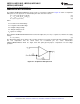
A pulse generator is shown in Figure 64. Two diodes have been used to separate the charge and discharge
paths to capacitor C.
Figure 64. Pulse Generator
When the output voltage V
O
is first at its high, V
OH
, the capacitor C is charged toward V
OH
through R
2
. The
voltage across C rises exponentially with a time constant τ = R
2
C, and this voltage is applied to the inverting
input of the op amp. Meanwhile, the voltage at the non-inverting input is set at the positive threshold voltage
(V
TH+
) of the generator. The capacitor voltage continually increases until it reaches V
TH+
, at which point the
output of the generator will switch to its low, V
OL
which 0V is in this case. The voltage at the non-inverting input is
switched to the negative threshold voltage (V
TH−
) of the generator. The capacitor then starts to discharge toward
V
OL
exponentially through R
1
, with a time constant τ = R
1
C. When the capacitor voltage reaches V
TH−
, the output
of the pulse generator switches to V
OH
. The capacitor starts to charge, and the cycle repeats itself.
24 Submit Documentation Feedback Copyright © 2000–2013, Texas Instruments Incorporated
Product Folder Links: LMV321-N LMV321-N-Q1 LMV358-N LMV358-N-Q1 LMV324-N LMV324-N-Q1