
Datasheet


+
-
LMP7721
I
in
LIGHT
R
F
C
F
V
out
LMP7721
www.ti.com
SNOSAW6D –JANUARY 2008–REVISED MARCH 2013
Using the smaller capacitors will give much higher bandwidth with little degradation of transient response. It may
be necessary in any of the above cases to use a somewhat larger feedback capacitor to allow for unexpected
stray capacitance, or to tolerate additional phase shifts in the loop, or excessive capacitive load, or to decrease
the noise or bandwidth, or simply because the particular circuit implementation needs more feedback
capacitance to be sufficiently stable. For example, a printed circuit board’s stray capacitance may be larger or
smaller than the breadboard’s, so the actual optimum value for C
F
may be different from the one estimated using
the breadboard. In most cases, the values of C
F
should be checked on the actual circuit, starting with the
computed value.
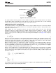
TRANSIMPEDANCE AMPLIFIER EXAMPLE (INVERTING CONFIGURATION)
A transimpedance amplifier converts a small amount of current into voltage. The transfer function of a
transimpedance amplifier is V
out
= −I
in
* R
F
. Figure 48 shows a typical transimpedance amplifier.
Figure 48. Photodiode Transimpedance Amplifier
The current is generated by a photodiode. The amount of the current is so small that it requires a large gain from
the transimpedance amplifier in order to transform the miniscule current into easily detectable voltages. The
larger the gain, the larger the value of R
F
needed. When R
F
is larger, the error caused by I
bias
*R
F
increases. For
example, if R
F
is 1000 MΩ, and an op amp with 3 nA of I
bias
is used, the I
bias
*R
F
error at the output will be 3V!
This error can be dramatically reduced to 3 µV by using the LMP7721.
Photodiodes are high impedance sensors which require careful design of the associated signal conditioning
circuitry in order to meet the system challenges. CMOS input op amps are often used in transimpedance
applications as they have extremely high input impedance. A triaxial cable is recommended for its very low noise
pick-up.
A MOS input stage with ultra low input bias current, negligible input current noise, and low input voltage noise
allows the LMP7721 to provide high fidelity amplification. In addition, the LMP7721 has a 17 MHz gain bandwidth
product, which enables high gain at wide bandwidth. A rail-to-rail output swing at 5.5V power supply allows
detection and amplification of a wide range of input currents. These properties make the LMP7721 ideal for
transimpedance amplification.
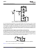
Figure 49 is an example of the LMP7721 used as a transimpedance amplifier.
Copyright © 2008–2013, Texas Instruments Incorporated Submit Documentation Feedback 17
Product Folder Links: LMP7721