
Datasheet


V
OUT
+
-
V
IN
+5V
-5V
C
POS
6.8 µF
R
G
R
F
0.01 µF
6.8 µF
C
NEG
0.01 µF
R
IN
0.1 µF
C
SS
A
V
= 1 +R
F
/R
G
= V
OUT
/V
IN
V
OUT
+
-
V
IN
+5V
-5V
C
POS
6.8 µF
R
G
R
F
0.01 µF
6.8 µF
C
NEG
0.01 µF
R
T
25:
0.1 µF
C
SS
SELECT R
T
TO
YIELD DESIRED
R
IN
= R
T
||R
G
A
V
=
V
OUT
V
IN
R
F
R
G
=
LMH6738
www.ti.com
SNOSAC1E –APRIL 2004–REVISED MARCH 2013
APPLICATION INFORMATION
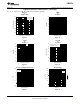
Figure 22. Recommended Non-Inverting Gain Figure 23. Recommended Inverting Gain Circuit
Circuit
GENERAL INFORMATION
The LMH6738 is a high speed current feedback amplifier, optimized for very high speed and low distortion. The
LMH6738 has no internal ground reference so single or split supply configurations are both equally useful.
EVALUATION BOARDS
Texas Instruments provides the following evaluation boards as a guide for high frequency layout and as an aid in
device testing and characterization. Many of the data sheet plots were measured with these boards.
Device Package Evaluation Board
Part Number
LMH6738MQA SSOP LMH730275
FEEDBACK RESISTOR SELECTION
One of the key benefits of a current feedback operational amplifier is the ability to maintain optimum frequency
response independent of gain by using appropriate values for the feedback resistor (R
F
). The Electrical
Characteristics and Typical Performance plots specify an R
F
of 550Ω, a gain of +2 V/V and ±5V power supplies
(unless otherwise specified). Generally, lowering R
F
from it’s recommended value will peak the frequency
response and extend the bandwidth while increasing the value of R
F
will cause the frequency response to roll off
faster. Reducing the value of R
F
too far below it’s recommended value will cause overshoot, ringing and,
eventually, oscillation.
Copyright © 2004–2013, Texas Instruments Incorporated Submit Documentation Feedback 9
Product Folder Links: LMH6738