
Datasheet


R
G
R
G
V
CM
R
L
V
OUT
R
F
R
F
C
L
R
O
R
O
V
CLAMP
+
-
V
IN
a
V
O
1
V
O
2
V
I
2
V
I
1
R
M
R
T
R
S
V
ICM
= V
OCM
V
ICM
=
V
I
1 + V
I
2
2
*V
CM
=
V
O
1 + V
O
2
2
*BY DESIGN
+
-
LMH6553
SNOSB07H –SEPTEMBER 2008–REVISED MARCH 2013
www.ti.com
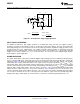
Figure 58. AC Coupled for Single Supply Operation
SPLIT SUPPLY OPERATION
For optimum performance, split supply operation is recommended using +5V and −5V supplies; however,
operation is possible on split supplies as low as +2.25V and −2.25V and as high as +6V and −6V. Provided the
total supply voltage does not exceed the 4.5V to 12V operating specification, asymmetric supply operation is also
possible and in some cases advantageous. For example, if 5V DC coupled operation is required for low power
dissipation but the amplifier input common mode range prevents this operation, it is still possible with split
supplies of (V
+
) and (V
−
). Where (V
+
) - (V
−
) = 5V and V
+
and V
−
are selected to set the amplifier input common
mode voltage to suit the application.
CLAMP OPERATION
The output clamp allows control of the maximum amplifier output swing to prevent overdriving of following stages
such as sensitive ADC inputs and provide fast recovery from signal transients that would otherwise saturate the
signal path. Figure 59 shows the relationship between V
CLAMP
and the +OUT and −OUT outputs. The example
circuit shown has a single ended input and is set for a gain of 2 V/V. For proper operation V
CM
< V
CLAMP
< V
CM
+
2.0V and the upper single ended output voltage is limited to the voltage level set at the V
CLAMP
input. The output
common mode control loop forces the lower single ended voltage to be limited to 2*V
CM
- V
CLAMP
. The maximum
clamped single ended output swing is therefore equal to 2*(V
CLAMP
- V
CM
) and the maximum differential output
swing is therefore equal to 4*(V
CLAMP
- V
CM
). In the example of Figure 59 with V
CLAMP
set to 2V and V
CM
set to
1.5V, the maximum single ended output is therefore 1 V
PP
centered at 1.5V and the maximum differential output
is 2 V
PP
. This is shown for the case of a 2 V
PP
input sine wave which for a gain of 2 V/V in unclamped operation
would provide single ended outputs at +OUT and -OUT of 2 V
PP
but is shown being clamp limited to 1 V
PP
.
22 Submit Documentation Feedback Copyright © 2008–2013, Texas Instruments Incorporated
Product Folder Links: LMH6553