
Datasheet


LMC6462, LMC6464
SNOS725D –MAY 1999–REVISED MARCH 2013
www.ti.com
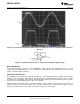
• Frequency and transient response
• GBW dependence on loading conditions
• Quiescent and dynamic supply current
• Output swing dependence on loading conditions
and many more characteristics as listed on the macromodel disk.
Contact the Texas Instruments Customer Response Center to obtain an operational amplifier Spice model library
disk
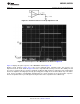
Printed-Circuit-Board Layout for High-Impedance Work
It is generally recognized that any circuit which must operate with less than 1000 pA of leakage current requires
special layout of the PC board. When one wishes to take advantage of the ultra-low input current of the
LMC6462/4, typically 150 fA, it is essential to have an excellent layout. Fortunately, the techniques of obtaining
low leakages are quite simple. First, the user must not ignore the surface leakage of the PC board, even though
it may sometimes appear acceptably low, because under conditions of high humidity or dust or contamination,
the surface leakage will be appreciable.
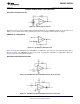
To minimize the effect of any surface leakage, lay out a ring of foil completely surrounding the LMC6462's inputs
and the terminals of capacitors, diodes, conductors, resistors, relay terminals, etc. connected to the op-amp's
inputs, as in Figure 43. To have a significant effect, guard rings should be placed in both the top and bottom of
the PC board. This PC foil must then be connected to a voltage which is at the same voltage as the amplifier
inputs, since no leakage current can flow between two points at the same potential. For example, a PC board
trace-to-pad resistance of 10
12
Ω, which is normally considered a very large resistance, could leak 5 pA if the
trace were a 5V bus adjacent to the pad of the input. This would cause a 30 times degradation from the
LMC6462/4's actual performance. However, if a guard ring is held within 5 mV of the inputs, then even a
resistance of 10
11
Ω would cause only 0.05 pA of leakage current. See Figure 44 through Figure 46 for typical
connections of guard rings for standard op-amp configurations.
Figure 43. Example of Guard Ring in P.C. Board Layout
16 Submit Documentation Feedback Copyright © 1999–2013, Texas Instruments Incorporated
Product Folder Links: LMC6462 LMC6464