
Datasheet


Table Of Contents
LMC6044
SNOS612D –NOVEMBER 1994–REVISED MARCH 2013
www.ti.com
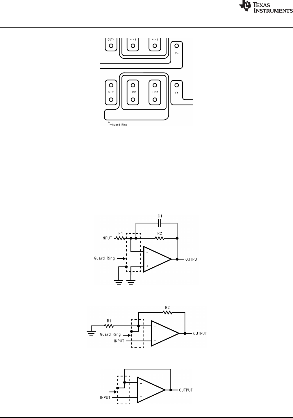
Figure 30. Example of Guard Ring in P.C. Board Layout
To minimize the effect of any surface leakage, lay out a ring of foil completely surrounding the LMC6044's inputs
and the terminals of capacitors, diodes, conductors, resistors, relay terminals, etc. connected to the op-amp's
inputs, as in Figure 30. To have a significant effect, guard rings should be placed on both the top and bottom of
the PC board. This PC foil must then be connected to a voltage which is at the same voltage as the amplifer
inputs, since no leakage current can flow between two points at the same potential. For example, a PC board
trace-to-pad resistance of 10
12
Ω, which is normally considered a very large resistance, could leak 5 pA if the
trace were a 5V bus adjacent to the pad of the input. This would cause a 100 times degradation from the
LMC6044's actual performance. However, if a guard ring is held within 5 mV of the inputs, then even a
resistance of 10
11
Ω would cause only 0.05 pA of leakage current. See Figure 33 for typical connections of guard
rings for standard op-amp configurations.
Figure 31. Inverting Amplifier Typical Connections of Guard Rings
Figure 32. Non-Inverting Amplifier Typical Connections of Guard Rings
Figure 33. Follower Typical Connections of Guard Rings
12 Submit Documentation Feedback Copyright © 1994–2013, Texas Instruments Incorporated
Product Folder Links: LMC6044