
Datasheet


D7 D6 D5 D4 D3 D2 D1 D0
1 9 1 9
Ack
by
LM95235
Start by
Master
Repeat
Start by
Master
Frame 1
Serial Bus Address Byte
Frame 2
Command Byte
Ack
by
LM95235
D7 D6 D5 D4 D3 D2 D1 D0
1 9 1 9
Ack
by
LM95235
Frame 3
Serial Bus Address Byte
Frame 4
Data Byte from the LM95235
No Ack
by
Master
Stop
by
Master
SMBCLK
SMBDAT
SMBCLK
(Continued)
SMBDAT
(Continued)
R/W
A5 A3 A2 A0A6 A4 A1
R/W
A5 A3 A2 A0A6 A4 A1
LM95235
LM95235-Q1
www.ti.com
SNIS142F –APRIL 2006–REVISED MARCH 2013
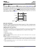
Figure 17. SMBus Timing Diagram for Access of Data (Default Address of 4Ch is shown)
(d) Serial Bus Write Followed by a Repeat Start and Immediate Read
SERIAL INTERFACE RESET
In the event that the SMBus Master is RESET while the LM95235 is transmitting on the SMBDAT line, the
LM95235 must be returned to a known state in the communication protocol. This may be done in one of two
ways:
1. When SMBDAT is LOW, the LM95235 SMBus state machine resets to the SMBus idle state if either
SMBDAT or SMBCLK are held low for more than 35 ms (t
TIMEOUT
). Note that according to SMBus
specification 2.0 all devices are to timeout when either the SMBCLK or SMBDAT lines are held low for 25 -
35 ms. Therefore, to insure a timeout of all devices on the bus the SMBCLK or SMBDAT lines must be held
low for at least 35 ms.
2. When SMBDAT is HIGH, have the master initiate an SMBus start. The LM95235 will respond properly to an
SMBus start condition at any point during the communication. After the start the LM95235 will expect an
SMBus Address address byte.
ONE-SHOT CONVERSION
The One-Shot register is used to initiate a single conversion and comparison cycle when the device is in standby
mode, after which the device returns to standby. This is not a data register and it is the write operation that
causes the one-shot conversion. The data written to this address is irrelevant and is not stored. A zero will
always be read from this register.
Copyright © 2006–2013, Texas Instruments Incorporated Submit Documentation Feedback 17
Product Folder Links: LM95235 LM95235-Q1