
Datasheet


LM95214
SNIS146A –MARCH 2007–REVISED MARCH 2013
www.ti.com
1. All Temperature readings set to 0°C until the end of the first conversion
2. Remote offset for all channels 0°C
3. Configuration: Active converting, Fault Queue enabled for Remote 3 and 4
4. Continuous conversion with all channels enabled, time = 1s
5. Enhanced digital filter enabled for Remote 1 and 2
6. Status Registers depends on state of thermal diode inputs
7. Local and Remote Temperature Limits for TCRIT1, TCRIT2 and TCRIT3 outputs:
Output Pin Temperature Channel Limit
Remote 4 Remote 3 Remote 2 Remote 1 Local
(°C) (°C) (°C) (°C) (°C)
TCRIT1 Masked, Masked, 110 110 Masked,
85 85 85
TCRIT2 85 85 85 85 85
TCRIT3 85 85 Masked, Masked, Masked,
85 85 85
8. Manufacturers ID set to 01h
9. Revision ID set to 7Bh
SMBus INTERFACE
The LM95214 operates as a slave on the SMBus, so the SMBCLK line is an input and the SMBDAT line is
bidirectional. The LM95214 never drives the SMBCLK line and it does not support clock stretching. According to
SMBus specifications, the LM95214 has a 7-bit slave address. Three SMBus device address can be selected by
connecting A0 (pin 6) to either Low, Mid-Supply or High voltages. The LM95214 has the following SMBus slave
address:
A0 Pin State SMBus Device Address A[6:0]
Hex Binary
Low 18h 001 1000
Mid-Supply 4Dh 100 1101
High 4Eh 100 1110
TEMPERATURE CONVERSION SEQUENCE
Each of the 5 temperature channels of LM95214 can be turned OFF independent from each other via the
Channel Enable Register. Turning off unused channels will increase the conversion speed in the fastest
conversion speed mode. If the slower conversion speed settings are used, disabling unused channels will reduce
the average power consumption of LM95214.
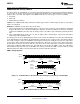
Digital Filter
In order to suppress erroneous remote temperature readings due to noise as well as increase the resolution of
the temperature, the LM95214 incorporates a digital filter for Remote 1 and 2 Temperature Channels. When a
filter is enabled the filtered readings are used for the TCRIT comparisons. There are two possible digital filter
settings that are enabled through the Filter Setting Register at register address 0Fh. The filter for each channel
can be set according to the following table:
12 Submit Documentation Feedback Copyright © 2007–2013, Texas Instruments Incorporated
Product Folder Links: LM95214