LM84 LM84 Diode Input Digital Temperature Sensor with Two-Wire Interface Literature Number: SNIS108B
LM84 Diode Input Digital Temperature Sensor with Two-Wire Interface General Description The LM84 is a remote diode temperature sensor, Delta-Sigma analog-to-digital converter, and digital over-temperature detector with an SMBus™ interface. The LM84 senses its own temperature as well as the temperature of a target IC with a diode junction, such as a Pentium ® II processor or a diode connected 2N3904. A diode junction (semiconductor junction) is required on the target IC’s die.
LM84 Connection Diagram QSOP-16 DS100961-2 TOP VIEW Ordering Information Order Number NS Package Number Transport Media LM84BIMQA MQA16A (QSOP-16) LM84BIMQAX LM84CIMQA LM84CIMQAX SMBus Revision Level Noise Filter on SMBCLK 95 Units in Rail 1.1 20MHz MQA16A (QSOP-16) 2500 Units on Tape and Reel 1.1 20MHz MQA16A (QSOP-16) 95 Units in Rail 1.0 Not Available MQA16A (QSOP-16) 2500 Units on Tape and Reel 1.0 Not Available Typical Application DS100961-3 www.national.
LM84 Pin Descriptions Label Pin # Function Typical Connection Manufacturing test pins. NC 1, 5, 9, 13, 16 VCC 2 D+ 3 D− Positive Supply Voltage Input Left floating. PC board traces may be routed through the pads for these pins. Although, the components that drive these traces should share the same supply as the LM84 so that the Absolute Maximum Voltage at any Pin rating is not violated. DC Voltage from 3.0V to 3.6V Diode Current Source To Diode Anode.
LM84 Absolute Maximum Ratings (Note 1) Supply Voltage Voltage at Any Pin: NC (Pins 1,5,9), ADD0, ADD1, D+ All other pins (except D−) D− Input Current Input Current at All Other Pins (Note 2) Package Input Current (Note 2) SMBData, T_CRIT_A Output Sink Current Output Voltage Storage Temperature Soldering Information, Lead Temperature QSOP Package (Note 3) Vapor Phase (60 seconds) Infrared (15 seconds) ESD Susceptibility (Note 4) Human Body Model Machine Model −0.3V to 6.0V −0.3V to (VCC + 0.3V) −0.
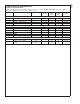
Symbol Parameter Conditions Typical LM84B LM84C Units (Note 6) Limits (Note 7) Limits (Note 7) (Limit) SMBData, SMBCLK VIN(1) Logical “1” Input Voltage 2.1 1.4 V (min) VIN(0) Logical “0”Input Voltage 0.8 0.6 V (max) IIN(1) Logical “1” Input Current VIN = VCC 0.005 1.0 1.0 µA (max) IIN(0) Logical “0” Input Current VIN = 0V −0.005 −1.0 −1.0 µA (max) ADD0, ADD1 VIN(1) Logical “1” Input Voltage VCC 1.6 1.6 V (min) VIN(0) Logical “0”Input Voltage GND 0.5 0.
LM84 Logic Electrical Characteristics (Continued) SMBus DIGITAL SWITCHING CHARACTERISTICS Unless otherwise noted, these specifications apply for VCC =+3.0 Vdc to +3.6 Vdc, CL (load capacitance) on output lines = 80 pF. Boldface limits apply for TA = TJ = TMIN to TMAX; all other limits TA = TJ = +25˚C, unless otherwise noted. The switching characteristics of the LM84 fully meet or exceed the published specifications of the SMBus or I2C bus.
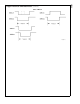
LM84 Logic Electrical Characteristics (Continued) SMBus TIMEOUT DS100961-13 7 www.national.
LM84 Logic Electrical Characteristics (Continued) Note 1: Absolute Maximum Ratings indicate limits beyond which damage to the device may occur. DC and AC electrical specifications do not apply when operating the device beyond its rated operating conditions. Note 2: When the input voltage (VI) at any pin exceeds the power supplies (VI < GND or VI > VCC), the current at that pin should be limited to 5 mA.
LM84 Logic Electrical Characteristics (Continued) DS100961-5 FIGURE 2. Temperature-to-Digital Transfer Function (Non-linear scale for clarity) 1.0 Functional Description The LM84 temperature sensor incorporates a band-gap type temperature sensor using a Local or Remote diode and an 8-bit ADC (Delta-Sigma Analog-to-Digital Converter). The LM84 is compatible with the serial SMBus and I2C interfaces.
LM84 1.0 Functional Description minimize any local temperature reading errors due to self heating of the LM84. The maximum resistance of the pull-up, based on LM84 specification for High Level Output Current, to provide a 2V high level, is 30 kΩ. (Continued) 1.3 SMBus INTERFACE The LM84 operates as a slave on the SMBus, so the SMBCLK line is an input (no clock is generated by the LM84) and the SMBData line is bi-directional. According to SMBus specifications, the LM84 has a 7-bit slave address.
LM84 1.0 Functional Description (Continued) 1.7 COMMUNICATING with the LM84 DS100961-9 1.7.1 SMBus TIMEOUT The LM84 SMBus interface circuitry will be reset to the SMBus idle state if the SMBData or SMBCLK lines are held low for more than 40 ms. The LM84 may or may not reset the state SMBData or SMBCLK if either of these lines are held low between 25 ms and 40 ms. Holding SMBData or SMBCLK low for less than or equal to 25 ms will not reset the interface circuitry.
LM84 1.0 Functional Description (Continued) 1.8 LM84 REGISTERS 1.8.1 COMMAND REGISTER Selects which registers will be read from or written to. Data for this register should be transmitted during the Command Byte of the SMBus write communication.
LM84 1.0 Functional Description (Continued) 1.8.6 LOCAL AND REMOTE T_CRIT REGISTERS (Read/Write): D7 D6 D5 D4 D3 D2 D1 D0 MSB Bit 6 Bit 5 Bit 4 Bit 3 Bit 2 Bit 1 LSB D7–D0: RT_CRIT and LT_CRIT setpoint temperature data. Power up default is LT_CRIT = RT_CRIT = 127˚C. 2.
LM84 3.0 Application Hints The LM84 can be applied easily in the same way as other integrated-circuit temperature sensors, and its remote diode sensing capability allows it to be used in new ways as well. It can be soldered to a printed circuit board, and because the path of best thermal conductivity is between the die and the pins, its temperature will effectively be that of the printed circuit board lands and traces soldered to the LM84’s pins.
7. with the sense diode. For the Pentium II this would be pin A14. (Continued) The ideal place to connect the LM84’s GND pin is as close as possible to the Processors GND associated DS100961-15 FIGURE 6. Recommended Diode Trace Layout Noise on the digital lines, overshoot greater than VCC and undershoot less than GND, may prevent successful SMBus communication with the LM84. SMBus no acknowledge is the most common symptom, causing unnecessary traffic on the bus.
LM84 Diode Input Digital Temperature Sensor with Two-Wire Interface Physical Dimensions inches (millimeters) unless otherwise noted 16-Lead QSOP Package Order Number LM84BIMQA, LM84BIMQAX, LM84CIMQA or LM84CIMQAX NS Package Number MQA16 LIFE SUPPORT POLICY NATIONAL’S PRODUCTS ARE NOT AUTHORIZED FOR USE AS CRITICAL COMPONENTS IN LIFE SUPPORT DEVICES OR SYSTEMS WITHOUT THE EXPRESS WRITTEN APPROVAL OF THE PRESIDENT AND GENERAL COUNSEL OF NATIONAL SEMICONDUCTOR CORPORATION. As used herein: 1.
IMPORTANT NOTICE Texas Instruments Incorporated and its subsidiaries (TI) reserve the right to make corrections, modifications, enhancements, improvements, and other changes to its products and services at any time and to discontinue any product or service without notice. Customers should obtain the latest relevant information before placing orders and should verify that such information is current and complete.