
Datasheet


LM82
SNIS113D –JANUARY 2000–REVISED MARCH 2013
www.ti.com
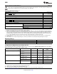
Figure 8. INT output related circuitry logic diagram
The INT output can be disabled by setting the INT mask bit, D7, of the configuration register. INT can be
programmed to be active high or low by the state of the INT inversion bit, D1, in the configuration register. A “0”
would program INT to be active low. INT is an open-drain output.
T_CRIT_A OUTPUT and T_CRIT LIMIT
T_CRIT_A is activated when any temperature reading is greater than the limit preset in the critical temperature
setpoint register (T_CRIT), as shown in Figure 9. The Status Registers can be read to determine which event
caused the alarm. A bit in the Status Registers is set high to indicate which temperature reading exceeded the
T_CRIT setpoint temperature and caused the alarm, see STATUS REGISTER.
Local and remote temperature diodes are sampled in sequence by the A/D converter. The T_CRIT_A output and
the Status Register flags are updated at the completion of a conversion. T_CRIT_A and the Status Register flags
are reset only after the Status Register is read and if a temperature conversion is below the T_CRIT setpoint, as
shown in Figure 9. Figure 10 shows a simplified logic diagram of the T_CRIT_A and related circuitry.
* Note: Status Register Bits are reset by a read of Status Register where bit is located.
Figure 9. T_CRIT_A Temperature Response Diagram
10 Submit Documentation Feedback Copyright © 2000–2013, Texas Instruments Incorporated
Product Folder Links: LM82