
Datasheet


LM6588
www.ti.com
SNOSA77D –MAY 2003–REVISED MARCH 2013
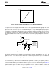
Unity Gain
The unity gain or voltage-follower configuration is the most subject to oscillation. If a part is stable at unity gain it
is almost certain to work in other configurations. In certain applications where the part is setting a reference
voltage or is being used as a buffer greater stability can be achieved by configuring the part as a gain of −1 or −2
or +2.
Phase Margin
The phase margin of an op amps gain-phase plot is an indication of the stability of the amp. It is desirable to
have at least 45°C of phase margin to insure stability in all cases. The LM6588 has 60°C of phase margin even
with it’s large output currents and Rail-to-Rail output stage, which are generally more prone to stability issues.
Capacitive Load
The LM6588 can withstand 30pF of capacitive load in a unity gain configuration before stability issues arise. At
very large capacitances, the load capacitor will attenuate the gain like any other heavy load and the part
becomes stable again. The LM6588 will be stable at 330nF and higher load capacitance. Refer to the chart in the
Typical Performance Characteristics section.
OUTPUT
Swing vs. Current
The LM6588 will get to about 25mV or 30mV of either rail when there is no load. The LM6588 can sink or source
hundreds of milliamperes while remaining less then 0.5V away from the rail. It should be noted that if the outputs
are driven to the rail and the part can no longer maintain the feedback loop, the internal circuitry will deliver large
base currents into the huge output transistors, trying to get the outputs to get past the saturation voltage. The
base currents will approach 16 milliamperes and this will appear as an increase in power supply current.
Operating at this power dissipation level for extended periods will damage the part, especially in the higher
thermal resistance TSSOP package. Because of this phenomenon, unused parts should not have the inputs
strapped to either rail, but should have the inputs biased at the midpoint or at least a diode drop (0.6V) within the
rails.
Self Heating
As discussed above the LM6588 is capable of significant power by virtue of its 200mA current handling
capability. A TSSOP package cannot sustain these power levels for more then a brief period.
TFT Display Application
INTRODUCTION
In today’s high-resolution TFT displays, op amps are used for the following three functions:
1. V
COM
Driver
2. Gamma Buffer
3. Panel Repair Buffer
All of these functions utilize op amps as non-inverting, unity-gain buffers. The V
COM
Driver and Gamma Buffer
are buffers that supply a well regulated DC voltage. A Panel Repair Buffer, on the other hand, provides a high
frequency signal that contains part of the display’s visual image.
In an effort to reduce production costs, display manufacturers use a minimum variety of different parts in their
TFT displays. As a result, the same type of op amp will be used for the V
COM
Driver, Gamma Buffer, and Panel
Repair Buffer. To perform all these functions, such an op amp must have the following characteristics:
1. Large output current drive
2. Rail to rail input common mode range
3. Rail to rail output swing
4. Medium speed gain bandwidth and slew rate
Copyright © 2003–2013, Texas Instruments Incorporated Submit Documentation Feedback 13
Product Folder Links: LM6588