
Datasheet


LM6181
www.ti.com
SNOS634B –MAY 1998–REVISED MAY 2013
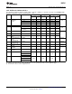
±15V AC Electrical Characteristics
The following specifications apply for Supply Voltage = ±15V, R
F
= 820Ω, R
L
= 1 kΩ unless otherwise noted. Boldface limits
apply at the temperature extremes; all other limits T
J
= 25°C.
Symbol Parameter Conditions LM6181AM LM6181AI LM6181I Units
Typical
(1)
Limit
(2)
Typical
(1)
Limit
(
Typical
(1)
Limit
(2)
2)
BW Closed Loop A
V
= +2 100 100 100 MHz
Bandwidth min
A
V
= +10 80 80 80
−3 dB
A
V
= −1 100 80 100 80 100 80
A
V
= −10 60 60 60
PBW Power Bandwidth A
V
= −1, V
O
= 5 V
PP
60 60 60
SR Slew Rate Overdriven 2000 2000 2000 V/μs
min
A
V
= −1, V
O
= ±10V, 1400 1000 1400 1000 1400 1000
R
L
= 150Ω
(3)
t
s
Settling Time (0.1%) A
V
= −1, V
O
= ±5V 50 50 50 ns
R
L
= 150Ω
t
r
, t
f
Rise and Fall Time V
O
= 1 V
PP
5 5 5
t
p
Propagation Delay V
O
= 1 V
PP
6 6 6
Time
i
n(+)
Non-Inverting Input f = 1 kHz 3 3 3 pA/√Hz
Noise
Current Density
i
n(−)
Inverting Input Noise f = 1 kHz 16 16 16 pA/√Hz
Current Density
e
n
Input Noise Voltage f = 1 kHz 4 4 4 pA/√Hz
Density
Second Harmonic 2 V
PP
, 10 MHz −50 −50 −50 dBc
Distortion
Third Harmonic 2 V
PP
, 10 MHz −55 −55 −50
Distortion
Differential Gain R
L
= 150Ω %
A
V
= +2 0.05 0.05 0.05
NTSC
Differential Phase R
L
= 150Ω Deg
A
V
= +2 0.04 0.04 0.04
NTSC
(1) Typical values represent the most likely parametric norm.
(2) All limits ensured at room temperature (standard type face) or at operating temperature extremes (bold face type).
(3) Measured from +25% to +75% of output waveform.
Copyright © 1998–2013, Texas Instruments Incorporated Submit Documentation Feedback 5
Product Folder Links: LM6181