
Datasheet


R
GATE
C
BOOT
HO
HS
LO
V
SS
HB
LM5104
L
(Optional external
fast recovery diode)
IN
V
DD
V
IN
V
CC
PWM
CONTROLLER
GND
V
DD
OUT1
OUT2
RT
C
LM5104
SNVS269C –JANUARY 2004–REVISED MARCH 2013
www.ti.com
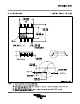
The total IC power dissipation can be estimated from the above plots by summing the gate drive losses with the
bootstrap diode losses for the intended application. Because the diode losses can be significant, an external
diode placed in parallel with the internal bootstrap diode (refer to Figure 22) can be helpful in removing power
from the IC. For this to be effective, the external diode must be placed close to the IC to minimize series
inductance and have a significantly lower forward voltage drop than the internal diode.
Figure 22. LM5104 Driving MOSFETs Connected in Synchronous Buck Configuration
12 Submit Documentation Feedback Copyright © 2004–2013, Texas Instruments Incorporated
Product Folder Links: LM5104