
Datasheet


CS
ARTN
RTN
OUT
R
SENSE
1 nF
100:
LM5072
+ CLK LEB
current sense
65 ns blanking
To PWM
Comparator
To Drain of Hot
Swap MOSFET
12
9
16
8
Isolation
5k
COMP
15
14
FB
SS
to PWM
16
ARTN
From
Secondary
Error-
Amplifier
5V
.1 25 V
LM5072
Boundary
5k
COMP
15
14
FB
SS
to PWM
R2
16
ARTN
R1
Vo
Zcomp
5V
.1 25V
LM5072
LM5072
www.ti.com
SNVS437D –MARCH 2006–REVISED APRIL 2013
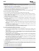
Figure 26. Internal Error Amplifier – Used for Non-isolated Output Applications
For isolated applications, the error amplifier function is located on the isolated secondary side. The LM5072’s
error amplifier can be disabled by connecting the FB pin to the ARTN pin. As shown in Figure 27, an opto-
coupler is normally used to send the feedback signal across the isolation boundary to the COMP pin. The
internal pull-up resistor on the COMP pin now serves as the pull-up bias for the opto-coupler transistor.
Figure 27. The Internal Error Amplifier – Bypassed in Isolated Output Applications
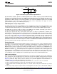
Current Sense and Limit
The LM5072 CS pin senses the transformer primary current signal for current mode control and current limiting of
the supply. As shown in Figure 28, the current sense function can be fulfilled by a simple sense resistor R
SENSE
inserted between the RTN and the source of the primary MOSFET switch.
The R
SENSE
resistor should be non-inductive, and a low pass filter should be used to reject the switching noise on
the sensed signal. A simple RC filter using 100Ω and 1 nF is typically sufficient. The filter capacitor must be
located close to the CS and ARTN pins. In order to prevent noise propagation and to improve the noise immunity
of the current sense, it is very important to minimize the return path of the current sense signal. This is
accomplished with direct connection to the ARTN pin and a single point connection to the RTN pin on the PC
Board layout.
Figure 28. Current Sense Schemes
Copyright © 2006–2013, Texas Instruments Incorporated Submit Documentation Feedback 21
Product Folder Links: LM5072