
Datasheet


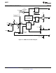
Table Of Contents
- FEATURES
- Packages
- DESCRIPTION
- Absolute Maximum Ratings
- Operating Ratings
- Electrical Characteristics
- Typical Performance Characteristics
- Specialized Block Diagrams
- Detailed Operating Description
- Modes of Operation
- Detection Signature
- Classification
- Undervoltage Lockout (UVLO)
- AUX Pin Operation
- Power Supply Operation
- High Voltage Start-up Regulator
- Error Amplifier
- Current Limit / Current Sense
- Oscillator, Shutdown and Sync Capability
- PWM Comparator / Slope Compensation
- Soft-Start
- Gate Driver and Maximum Duty Cycle Limit
- Thermal Protection
- LM5071 Application Circuit Diagrams
- Revision History

RSIG
RCLASS
AUX
UVLO
UVLORTN
V
EE
RTN
V
IN
RT
CS
COMP
FB
VCC
OUT
SS
ARTN
14
13
12
11
10
8 9
15
16
1
2
3
4
5
7
6
V
EE
LM5071
R
T
S
S
V
EE
OUT
V
IN
V
CC
CS
RTN
ARTN
RCLASS
V
IN
RSIG
SMPS
Controller
Internal
High Voltage
Regulator
Current Limit
Bandgap
Regulator
VIN < 10
V
Switch
5V
FB
+
-
UVLO
UVLORTN
AUX
+3.3V
COMP
Inrush /DC
LM5071
SNVS409E –NOVEMBER 2005–REVISED APRIL 2013
www.ti.com
Figure 1. Simplified Block Diagram
Connection Diagram
Figure 2. 16 Lead TSSOP
2 Submit Documentation Feedback Copyright © 2005–2013, Texas Instruments Incorporated
Product Folder Links: LM5071