
Datasheet


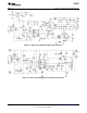


Table Of Contents
- FEATURES
- Packages
- DESCRIPTION
- Absolute Maximum Ratings
- Operating Ratings
- Electrical Characteristics
- Typical Performance Characteristics
- Specialized Block Diagrams
- Detailed Operating Description
- Modes of Operation
- Detection Signature
- Classification
- Undervoltage Lockout (UVLO)
- AUX Pin Operation
- Power Supply Operation
- High Voltage Start-up Regulator
- Error Amplifier
- Current Limit / Current Sense
- Oscillator, Shutdown and Sync Capability
- PWM Comparator / Slope Compensation
- Soft-Start
- Gate Driver and Maximum Duty Cycle Limit
- Thermal Protection
- LM5071 Application Circuit Diagrams
- Revision History

LM5071
SNVS409E –NOVEMBER 2005–REVISED APRIL 2013
www.ti.com
Thermal Protection
Internal thermal shutdown circuitry is provided to protect the integrated circuit in the event the maximum junction
temperature is exceeded. This feature prevents catastrophic failures from accidental device overheating. When
activated, typically at 165 degrees Celsius, the controller is forced into a low power standby state, disabling the
output driver, bias regulator, main interface pass MOSFET, and classification regulator if enabled. After the
temperature is reduced (typical hysteresis = 25°C) the V
CC
regulator will be enabled and a softstart sequence
initiated.
Thermal shutdown is not enabled during auxiliary power operation as the power MOSFET is not running any
current and should not experience an over-temperature condition. If the drain of the MOSFET exceeds 2.5V with
respect to VEE (internal Power Good de-assertion), PoE UVLO becomes de-asserted (insertion of PoE or other
48V supply), or the auxiliary power is removed, thermal limit will be re-enabled immediately.
LM5071 Application Circuit Diagrams
Figure 16. Single Isolated Output with Diode Rectification and 12V Auxiliary Supply
16 Submit Documentation Feedback Copyright © 2005–2013, Texas Instruments Incorporated
Product Folder Links: LM5071