
Datasheet


LM5045
SNVS699G –FEBRUARY 2011–REVISED MARCH 2013
www.ti.com
FUNCTIONAL DESCRIPTION
The LM5045 PWM controller contains all of the features necessary to implement a Full-Bridge topology power
converter using either current mode or voltage mode control. This device is intended to operate on the primary
side of an isolated dc-dc converter with input voltage up to 100V. This highly integrated controller-driver provides
dual 2A high and low side gate drivers for the four external bridge MOSFETs plus control signals for secondary
side synchronous rectifiers. External resistors program the leading and trailing edge dead-time between the main
and synchronous rectifier control signals. Intelligent startup of synchronous rectifier allows turn-on of the power
converter into the pre-bias loads. Cycle-by-cycle current limit protects the power components from load transients
while hiccup mode protection limits average power dissipation during extended overload conditions. Additional
features include programmable soft-start, soft-start of the synchronous rectifiers, and a 2 MHz capable oscillator
with synchronization capability and thermal shutdown.
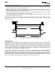
High-Voltage Start-Up Regulator
The LM5045 contains an internal high voltage start-up regulator that allows the input pin (VIN) to be connected
directly to the supply voltage over a wide range from 14V to 100V. The input can withstand transients up to
105V. When the UVLO pin potential is greater than 0.4V, the VCC regulator is enabled to charge an external
capacitor connected to the VCC pin. The VCC regulator provides power to the voltage reference (REF) and the
gate drivers (HO1/HO2 and LO1/LO2). When the voltage on the VCC pin exceeds its Under Voltage (UV)
threshold, the internal voltage reference (REF) reaches its regulation set point of 5V and the UVLO voltage is
greater than 1.25V, the soft-start capacitor is released and normal operation begins. The regulator output at VCC
is internally current limited. The value of the VCC capacitor depends on the total system design, and its start-up
characteristics. The recommended range of values for the VCC capacitor is 0.47μF to 10µF.
The internal power dissipation of the LM5045 can be reduced by powering VCC from an external supply. The
output voltage of the VCC regulator is initially regulated to 9.5V. After the synchronous rectifiers are engaged
(which is approximately when the output voltage in within regulation), the VCC voltage is reduced to 7.7V. In
typical applications, an auxiliary transformer winding is connected through a diode to the VCC pin. This winding
must raise the VCC voltage above 8V to shut off the internal start-up regulator. Powering VCC from an auxiliary
winding improves efficiency while reducing the controller’s power dissipation. The VCC UV circuit will still function
in this mode, requiring that VCC never falls below its UV threshold during the start-up sequence. The VCC
regulator series pass transistor includes a diode between VCC and VIN that should not be forward biased in
normal operation. Therefore, the auxiliary VCC voltage should never exceed the VIN voltage.
An external DC bias voltage can be used instead of the internal regulator by connecting the external bias voltage
to both the VCC and the VIN pins. This implementation is shown in the APPLICATIONS INFORMATION section.
The external bias must be greater than 10V and less than the VCC maximum voltage rating of 14V.
Line Under-Voltage Detector
The LM5045 contains a dual level Under-Voltage Lockout (UVLO) circuit. When the UVLO pin voltage is below
0.4V, the controller is in a low current shutdown mode. When the UVLO pin voltage is greater than 0.4V but less
than 1.25V, the controller is in standby mode. In standby mode the VCC and REF bias regulators are active
while the controller outputs are disabled. When the VCC and REF outputs exceed their respective under-voltage
thresholds and the UVLO pin voltage is greater than 1.25V, the soft-start capacitor is released and the normal
operation begins. An external set-point voltage divider from VIN to GND can be used to set the minimum
operating voltage of the converter. The divider must be designed such that the voltage at the UVLO pin will be
greater than 1.25V when VIN enters the desired operating range. UVLO hysteresis is accomplished with an
internal 20μA current sink that is switched on or off into the impedance of the set-point divider. When the UVLO
threshold is exceeded, the current sink is deactivated to quickly raise the voltage at the UVLO pin. When the
UVLO pin voltage falls below the 1.25V threshold, the current sink is enabled causing the voltage at the UVLO
pin to quickly fall. The hysteresis of the 0.4V shutdown comparator is internally fixed at 50mV.
The UVLO pin can also be used to implement various remote enable / disable functions. Turning off the
converter by forcing the UVLO pin to standby condition (0.4V < UVLO < 1.25V) provides a controlled soft-stop.
Refer to the Soft-Stop section for more details.
12 Submit Documentation Feedback Copyright © 2011–2013, Texas Instruments Incorporated
Product Folder Links: LM5045