
Datasheet


SW
FB
V
OUT
R2
LM5010A
R1
C2
L1
CB
CARA
SW
FB
LM5010A
V
OUT
Cff
R2
L1
R1
C2
R3
FB
SW
L1
C2
R3
LM5010A
R1
R2
V
OUT
LM5010A
LM5010A-Q1
SNVS376E –OCTOBER 2005–REVISED FEBRUARY 2013
www.ti.com
Figure 15. Low Ripple Output
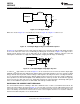
Where the circuit of Figure 15 is not suitable, the circuits of Figure 16 or Figure 17 can be used.
Figure 16. Low Output Ripple Using a Feed-Forward Capacitor
In Figure 16, Cff is added across R1 to AC-couple the ripple at V
OUT
directly to the FB pin. This allows the ripple
at V
OUT
to be reduced, in some cases considerably, by reducing R3. In the circuit of Figure 12, the ripple at V
OUT
ranged from 50 mVp-p at V
IN
= 6V to 320 mVp-p at V
IN
= 60V. By adding a 1000 pF capacitor at Cff and
reducing R3 to 0.75Ω, the V
OUT
ripple was reduced by 50%, ranging from 25 mVp-p to 160 mVp-p.
Figure 17. Low Output Ripple Using Ripple Injection
To reduce V
OUT
ripple further, the circuit of Figure 17 can be used. R3 has been removed, and the output ripple
amplitude is determined by C2’s ESR and the inductor ripple current. RA and CA are chosen to generate a 40-50
mVp-p sawtooth at their junction, and that voltage is AC-coupled to the FB pin via CB. In selecting RA and CA,
V
OUT
is considered a virtual ground as the SW pin switches between V
IN
and -1V. Since the on-time at SW varies
inversely with V
IN
, the waveform amplitude at the RA/CA junction is relatively constant. R1 and R2 must typically
be increased to more than 10k each to not significantly attenuate the signal provided to FB through CB. Typical
values for the additional components are RA = 200k, CA = 680 pF, and CB = 0.01 µF.
INCREASING THE CURRENT LIMIT THRESHOLD
The current limit threshold is nominally 1.25A, with a minimum value of 1.0A. If, at maximum load current, the
lower peak of the inductor current (I
PK-
in Figure 11) exceeds 1.0A, resistor R
CL
must be added between S
GND
and
I
SEN
to increase the current limit threshold to equal or exceed that lower peak current. This resistor diverts some
of the recirculating current from the internal sense resistor so that a higher current level is needed to switch the
internal current limit comparator. I
PK-
is calculated from:
16 Submit Documentation Feedback Copyright © 2005–2013, Texas Instruments Incorporated
Product Folder Links: LM5010A LM5010A-Q1