
Datasheet


LM4936
www.ti.com
SNAS269A –APRIL 2005–REVISED APRIL 2013
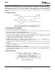
Figure 52. Headphone Sensing Circuit
HP SENSE FUNCTION ( Headphone In )
Applying a voltage between the V
IH
threshold shown in the graph found in the Typical Performance
Characteristics and V
DD
to the LM4936's HP SENSE control pin or loading a digital 1 into the HP Control bit (B4)
will change the output mode. The '+' outputs will change to be in phase with the '-' outputs instead of 180
degrees out of phase. This action mutes a bridged-connected load since the differential voltage across the load
is now close to 0V. The HP SENSE pin over rides the HP Control bit. See Table 2 for more info. Quiescent
current consumption is reduced when the IC is in this single-ended mode.
Figure 52 shows the implementation of the LM4936's headphone control function. With no headphones
connected to the headphone jack, the R1-R2 voltage divider sets the voltage applied to the HP SENSE pin at
approximately 50mV. This 50mV puts the LM4936 into bridged mode operation. The output coupling capacitor
blocks the amplifier's half supply DC voltage, protecting the headphones.
The HP SENSE threshold is set so the output signal cannot cause an output mode change. While the LM4936
operates in bridge mode, the DC potential across the load is essentially 0V. Connecting headphones to the
headphone jack disconnects the headphone jack contact pin from R2 and allows R1 to pull the HP SENSE pin
up to V
DD
through R4. This enables the headphone function and mutes the bridged speaker. The single-ended '-'
outputs then drive the headphones, whose impedance is in parallel with resistors R2 and R3. These resistors
have negligible effect on the LM4936's output drive capability since the typical impedance of headphones is 32Ω.
Figure 52 also shows the suggested headphone jack electrical connections. The jack is designed to mate with a
three-wire plug. The plug's tip and ring should each carry one of the two stereo output signals, whereas the
sleeve should carry the ground return. A headphone jack with one control pin contact is sufficient to drive the HP-
IN pin when connecting headphones.
GAIN SELECT FUNCTION (Bass Boost)
The LM4936 features selectable gain, using either internal or external feedback resistors. The GAIN SEL bit (B3)
controls which gain is selected. Loading a digital 0 into the GAIN SEL bit sets the gain to internal resulting in a
gain of 6dB for BTL mode or unity for singled-ended mode. Loading a digital 1 into the GAIN SEL bit sets the
gain to be determined by the external resistors, R
I
and R
F
.
In some cases a designer may want to improve the low frequency response of the bridged amplifier or
incorporate a bass boost feature. This bass boost can be useful in systems where speakers are housed in small
enclosures. A resistor, R
BS
, and a capacitor, C
BS
, in parallel, can be placed in series with the feedback resistor of
the bridged amplifier as seen in Figure 3.
At low, frequencies C
BS
is a virtual open circuit and at high frequencies, its nearly zero ohm impedance shorts
R
BS
. The result is increased bridge-amplifier gain at low frequencies. The combination of R
BS
and C
BS
form a -
6dB corner frequency at
f
C
= 1/(2πR
BS
C
BS
) (9)
The bridged-amplifier low frequency differential gain is:
Copyright © 2005–2013, Texas Instruments Incorporated Submit Documentation Feedback 23
Product Folder Links: LM4936