
Datasheet


LM4050-N, LM4050-N-Q1
SNOS455E –MAY 2000–REVISED APRIL 2013
www.ti.com
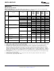
LM4050-N-5.0
Electrical Characteristics
Boldface limits apply for T
A
= T
J
= T
MIN
to T
MAX
; all other limits T
A
= T
J
= 25°C. The grades A, B and C designate initial
Reverse Breakdown Voltage tolerances of ±0.1%, ±0.2% and 0.5% respectively.
LM4050- LM4050- LM4050-
NAIM3 NBIM3 NCIM3
Units
Symbol Parameter Conditions Typical
(1)
LM4050- LM4050- LM4050-
(Limit)
NAEM3 NBEM3 NCEM3
Limits
(2)
Limits
(2)
Limits
(2)
V
R
Reverse Breakdown Voltage I
R
= 100 μA 5.000 V
Reverse Breakdown Voltage I
R
= 100 μA ±5.0 ±10 ±25 mV (max)
Tolerance
(3)
Industrial Temp. Range ±22 ±27 ±42 mV (max)
Extended Temp. Range ±30 ±35 ±50 mV (max)
I
RMIN
Minimum Operating Current 56 μA
74 74 74 μA (max)
Industrial Temp. Range 80 80 80 μA (max)
Extended Temp. Range 90 90 90 μA (max)
ΔV
R
/ΔT Average Reverse Breakdown I
R
= 10 mA ±30 ppm/°C
Voltage Temperature Coefficient
(3)
I
R
= 1 mA ±20 ppm/°C
I
R
= 100 μA ±20 ±50 ±50 ±50 ppm/°C (max)
ΔV
R
/ΔI
R
Reverse Breakdown Voltage I
RMIN
≤ I
R
≤ 1 mA 0.2 mV
Change with Operating Current
1.0 1.0 1.0 mV (max)
Change
(4)
1.4 1.4 1.4 mV (max)
1 mA ≤ I
R
≤ 15 mA 2.0 mV
8.0 8.0 8.0 mV (max)
12.0 12.0 12.0 mV (max)
Z
R
Reverse Dynamic Impedance I
R
= 1 mA, f = 120 Hz, 0.5 Ω
I
AC
= 0.1 I
R
Ω (max)
e
N
Wideband Noise I
R
= 100 μA 93
μV
rms
10 Hz ≤ f ≤ 10 kHz
ΔV
R
Reverse Breakdown Voltage Long t = 1000 hrs 120
Term Stability T = 25°C ±0.1°C ppm
I
R
= 100 μA
V
HYST
Thermal Hysteresis
(5)
ΔT = −40°C to 125°C 1.4 mV
(1) Typicals are at T
J
= 25°C and represent most likely parametric norm.
(2) Limits are 100% production tested at 25°C. Limits over temperature are guaranteed through correlation using Statistical Quality Control
(SQC) methods. The limits are used to calculate National's AOQL.
(3) The boldface (over-temperature) limit for Reverse Breakdown Voltage Tolerance is defined as the room temperature Reverse
Breakdown Voltage Tolerance ±[(ΔV
R
/ΔT)(maxΔT)(V
R
)]. Where, ΔV
R
/ΔT is the V
R
temperature coefficient, maxΔT is the maximum
difference in temperature from the reference point of 25°C to T
MIN
or T
MAX
, and V
R
is the reverse breakdown voltage. The total over-
temperature tolerance for the different grades in the industrial temperature range where maxΔT = 65°C is shown below: A-grade:
±0.425% = ±0.1% ±50 ppm/°C × 65°C B-grade: ±0.525% = ±0.2% ±50 ppm/°C × 65°C C-grade: ±0.825% = ±0.5% ±50 ppm/°C ×
65°CTherefore, as an example, the A-grade LM4050-N-2.5 has an over-temperature Reverse Breakdown Voltage tolerance of ±2.5V ×
0.425% = ±11 mV.
(4) Load regulation is measured on pulse basis from no load to the specified load current. Output changes due to die temperature change
must be taken into account separately.
(5) Thermal hysteresis is defined as the difference in voltage measured at +25°C after cycling to temperature -40°C and the 25°C
measurement after cycling to temperature +125°C.
6 Submit Documentation Feedback Copyright © 2000–2013, Texas Instruments Incorporated
Product Folder Links: LM4050-N LM4050-N-Q1