
Datasheet


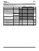


Cathode and Load Currents
R
S
+
ǒ
V
S
* V
Z
Ǔ
(
I
L
) I
Z
)
(1)
LM4040
I
Z
+ I
L
I
L
I
Z
V
S
V
Z
R
S
LM4040
SLOS456K – JANUARY 2005 – REVISED MARCH 2008 ..................................................................................................................................................
www.ti.com
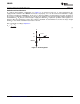
In a typical shunt-regulator configuration (see Figure 9 ), an external resistor, R
S
, is connected between the
supply and the cathode of the LM4040. R
S
must be set properly, as it sets the total current available to supply
the load (I
L
) and bias the LM4040 (I
Z
). In all cases, I
Z
must stay within a specified range for proper operation of
the reference. Taking into consideration one extreme in the variation of the load and supply voltage (maximum I
L
and minimum V
S
), R
S
must be small enough to supply the minimum I
Z
required for operation of the regulator, as
given by data-sheet parameters. At the other extreme, maximum V
S
and minimum I
L
, R
S
must be large enough
to limit I
Z
to less than its maximum-rated value of 15 mA.
R
S
is calculated according to Equation 1 :
Figure 9. Shunt Regulator
28 Submit Documentation Feedback Copyright © 2005 – 2008, Texas Instruments Incorporated