
Datasheet


t (s)
t (s)
I
L_AVG
I
SW_AVG
D*Ts Ts
D*Ts Ts
I
L
(A)
I
D
(A)
(a)
(b)
t (s)
D*Ts Ts
I
SW
(A)
(c)
I
D_AVG
= I
OUT_AVG
L
-
V
OUT
V
IN
L
V
IN
L
-
V
OUT
V
IN
L
V
IN
L
i'
+ +
PWM
V
OUT
V
IN
+
V
IN
-+
L
L
R
LOAD
+
-
V
OUT
+
V
IN
-+
L
R
LOAD
+
-
V
OUT
D1
D1
C
OUT
C
OUT
Q
C
OUT
LM3481
www.ti.com
SNVS346E –NOVEMBER 2007–REVISED APRIL 2012
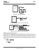
Figure 29. Simplified Boost Converter Diagram (a) First cycle of operation. (b) Second cycle of operation
POWER INDUCTOR SELECTION
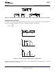
The inductor is one of the two energy storage elements in a boost converter. Figure 30 shows how the inductor
current varies during a switching cycle. The current through an inductor is quantified as:
Figure 30. a. Inductor current b. Diode current c. Switch current
If V
L
(t) is constant, di
L
(t)/dt must be constant. Hence, for a given input voltage and output voltage, the current in
the inductor changes at a constant rate.
Copyright © 2007–2012, Texas Instruments Incorporated Submit Documentation Feedback 15
Product Folder Links: LM3481