
Datasheet


S
e
= f
S
(V
SL
+ 50 x 10
-6
x R
SL
)
V
Ps
( )
'S
e
= 50 x 10
-6
x f
S
x R
SL
V
Ps
( )
'I
n
=
S
f
- S
e
S
n
+ S
e
'I
n-1
LM3477
www.ti.com
SNVS141K –OCTOBER 2000–REVISED MARCH 2013
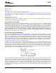
The subharmonic oscillation phenomenon is realized when a load excursion is experienced. The way it is
analyzed is to calculate how the inductor current settles after such an excursion. Take for example the case
when the inductor current experiences a step increase in its average current, shown as the dotted line in
Figure 22. In the switching period that the excursion occurs, the inductor current will change by ΔI
0
. In the
following switching period, the inductor current will have a difference ΔI
1
from its original starting value. The
original excursion is being propagated each switching cycle. What is desired is to find out if this propagation is
converging or diverging. It is apparent that the difference in the inductor current from one cycle to the next is a
function of S
n
, S
f
, and S
e
, as follows:
(1)
Hence, if the quantity (S
f
- S
e
)/(S
n
+ S
e
)is greater than 1, the inductor current diverges and subharmonic
oscillations result. Notice that as S
e
increases, the factor decreases. Also, when the duty cycle is greater than
50%, as the inductance become less, the factor increases.
The LM3477/A internally generates enough slope compensation S
e
to allow for the use of reasonable
inductances. The height of the compensation slope ramp V
SL
can be found in the Electrical Characteristics. The
LM3477/A incorporates a patented scheme to increase S
e
if there is need to use a smaller inductor. With the use
of a single resistor R
SL
, Se can be increased indefinitely. R
SL
increases the compensation slope Se by the
amount:
(2)
Therefore,
(3)
When excursions of the inductor current are divergent, the current sensing control loop is unstable and produces
a subharmonic oscillation in the inductor current. This oscillation is viewed as a resonance in the outer voltage
control loop at half the switching frequency. In POWER INDUCTOR SECTION, calculations for minimum
inductance and necessary slope resistance R
SL
are carried out based on this resonant peaking.
START-UP/SOFT-START
The LM3477/A incorporates an internal soft-start during start-up. The soft-start forces the inductor current to rise
slowly and smoothly as it increases towards the steady-state current. This technique is used to reduce the input
inrush current during soft-start. The soft-start functionality is effective for approximately the first 5ms of start-up.
NOTE
The LM3477/A will not start-up if the output voltage is biased by more than 200mV above
ground.
NOTE
If the slope resistor R
SL
is used, the hysteretic threshold will be lowered. Therefore, the
LM3477/A may require up to 100mA of pre-load to successfully start up.
SHORT CIRCUIT PROTECTION
When the voltage across the sense resistor (measured as the V
IN
− I
SEN
differential voltage) exceeds V
SC
, short-
circuit current limit gets activated. In the short-circuit protection mode, the external MOSFET is turned off. When
the short is removed, the external MOSFET is turned on after five cycles. The short circuit protection voltage V
SC
is specified in the Electrical Characteristics. V
SC
is lower in the LM3477A than in the LM3477.
SHUTDOWN
The compensation pin (Pin 2) of LM3477/A also functions as a shutdown pin. If a low signal (refer to the
Electrical Characteristics for definition of low signal) appears on the COMP/SD pin, the LM3477/A stops
switching and goes into a low supply current mode. The total supply current of the IC reduces to less than 10µA
under these conditions. Figure 23 shows different implementations of the shutdown function.
Copyright © 2000–2013, Texas Instruments Incorporated Submit Documentation Feedback 13
Product Folder Links: LM3477