
Datasheet


30127103
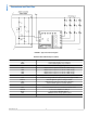
FIGURE 3. Changes of Rail Voltage Upon Power Up
Setting of V
DHC_READY
When V
RAIL
reaches V
DHC_READY
, the voltage at the VLedFB
pin of the LM3464A equals 2.5V. As the voltage at the
VLedFB pin reaches 2.5V, the LM3464A performs a test for
no long than 400uS to identify and exclude the idle (no LED
connected) or failed (shorten / open circuit of LED string) out-
put channels from the DHC loop. When a LED string is open
circuit, the voltage drop on the current sensing resistors
(V
SE1
— V
SE4
) is below 30mV. If the voltage of the SEx pin
maintains below 30mV longer than the fault detection time
defined by CFLT, an 'open fault' is recognized. When a LED
string is short circuit, causing the drain voltage of an external
MOSFET 8.4V higher than the drain voltage of any other
channel and maintains longer than the fault detection time
defined by CFLT, an short fault is recognized. Either a short
or open fault will cause the Faultb pin to pull low. When a LED
string experiences an open or short circuit, the corresponding
output channel will be disabled and excluded from the DHC
loop to sustain normal operation of the remaining LED strings.
The LM3464A will maintain the failed channels in disable
state until the EN pin is pulled low or the entire system is re-
powered. When the test is completed, the LM3464A enables
the output channels and provides constant current to the LED
strings.
The level of V
DHC_READY
is defined by the values of RFB1 and
RFB2 on the evaluation board and can be adjusted to any
level below 80V / 95V (LM3464/LM3464A) as desired. By de-
fault, the V
DHC_READY
is set at 48V. The V
DHC_READY
must set
no more than 20V higher than the forward voltages of any LED
string connected to the system under possible temperatures,
otherwise a ‘short fault’ may arise and results in immediate
output channel latch-off to protect the MOSFETs from over-
heat. The V
DHC_READY
is can be adjusted following equation
(5):
(5)
Adjusting Voltage Headroom
The voltage headroom of the LM3464A evaluation board can
be altered by adjusting the voltage at the VDHC pin (V
VDHC
)
in the range of 0.8V to 2V. For the applications with high rail
voltage ripple, the voltage headroom should be increased to
secure accurate output current regulation. By default, the VD-
HC pin is biased internally to 0.9V as shown in figure 4.
www.national.com 6
AN-2071