
Datasheet


LM117, LM317A, LM317-N
www.ti.com
SNVS774O –MAY 2004–REVISED JANUARY 2014
Table 1. θ
JA
Different Heatsink Area
Layout Copper Area Thermal Resistance
Top Side (in
2
)
(1)
Bottom Side (in
2
) (θ
JA
°C/W) TO-252
1 0.0123 0 103
2 0.066 0 87
3 0.3 0 60
4 0.53 0 54
5 0.76 0 52
6 1.0 0 47
7 0.066 0.2 84
8 0.066 0.4 70
9 0.066 0.6 63
10 0.066 0.8 57
11 0.066 1.0 57
12 0.066 0.066 89
13 0.175 0.175 72
14 0.284 0.284 61
15 0.392 0.392 55
16 0.5 0.5 53
(1) Tab of device attached to topside of copper.
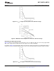
Figure 30. θ
JA
vs 2oz Copper Area for TO-252
Figure 31. Maximum Allowable Power Dissipation vs. Ambient Temperature for TO-252
Copyright © 2004–2014, Texas Instruments Incorporated Submit Documentation Feedback 15
Product Folder Links: LM117 LM317A LM317-N