
Datasheet


+
+
LG
HG
BOOT
LM2742
D1
C
BOOT
V
CC
5V
LM2742
www.ti.com
SNVS266C –MARCH 2004–REVISED MARCH 2013
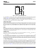
Figure 29. BOOT Supplied by Charge Pump
In a system without a separate, higher voltage, a charge pump (bootstrap) can be built using a diode and small
capacitor, Figure 29. The capacitor serves to maintain enough voltage between the top FET gate and source to
control the device even when the top FET is on and its source has risen up to the input voltage level.
The LM2742 gate drives use a BiCMOS design. Unlike some other bipolar control ICs, the gate drivers have rail-
to-rail swing, ensuring no spurious turn-on due to capacitive coupling.
POWER GOOD SIGNAL
The power good signal is the or-gated flag representing over-voltage and under-voltage protection. If the output
voltage is 18% over it's nominal value, V
FB
= 0.7V, or falls 30% below that value, V
FB
= 0.41V, the power good
flag goes low. It will return to a logic high whenever the feedback pin voltage is between 70% and 118% of 0.6V.
The power good pin is an open drain output that can be pulled up to logic voltages of 5V or less with a 10kΩ
resistor.
UVLO
The 4.2V turn-on threshold on V
CC
has a built in hysteresis of 0.6V. Therefore, if V
CC
drops below 3.6V, the chip
enters UVLO mode. UVLO consists of turning off the top FET, turning off the bottom FET, and remaining in that
condition until V
CC
rises above 4.2V. As with shutdown, the soft start capacitor is discharged through a FET,
ensuring that the next start-up will be smooth.
CURRENT LIMIT
Current limit is realized by sensing the voltage across the low side FET while it is on. The R
DSON
of the FET is a
known value, hence the current through the FET can be determined as:
V
DS
= I * R
DSON
(4)
The current through the low side FET while it is on is also the falling portion of the triangle wave inductor current.
The current limit threshold is determined by an external resistor, R
CS
, connected between the switch node and
the I
SEN
pin. A constant current of 50 µA is forced through R
CS
, causing a fixed voltage drop. This fixed voltage is
compared against V
DS
and if the latter is higher, the current limit of the chip has been reached. R
CS
can be found
by using the following equation:
R
CS
= R
DSON
(LOW) * I
LIM
/50µA (5)
For example, a conservative 15A current limit in a 10A design with a minimum R
DSON
of 10mΩ would require a
3.3kΩ resistor. Because current sensing is done across the low side FET, no minimum high side on-time is
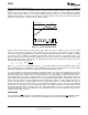
necessary. In the current limit mode the LM2727/37 will turn the high side off and the keep low side on for as
long as necessary. The LM2727/37 enters current limit mode if the inductor current exceeds the current limit
threshold at the point where the high side FET turns off and the low side FET turns on. (The point of peak
inductor current. See Figure 30.) Note that in normal operation mode the high side FET always turns on at the
Copyright © 2004–2013, Texas Instruments Incorporated Submit Documentation Feedback 13
Product Folder Links: LM2742