
Datasheet

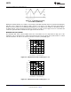


Table Of Contents
- FEATURES
- Applications
- DESCRIPTION
- Absolute Maximum Ratings
- Electrical Characteristics
- Typical Performance Characteristics
- Block Diagram
- Theory of Operation
- Application Hints
- SELECTING THE EXTERNAL CAPACITORS
- SELECTING THE OUTPUT CAPACITOR
- SELECTING THE INPUT CAPACITOR
- FEED-FORWARD COMPENSATION
- SELECTING DIODES
- LAYOUT HINTS
- SETTING THE OUTPUT VOLTAGE
- SWITCHING FREQUENCY
- DUTY CYCLE
- INDUCTANCE VALUE
- MAXIMUM SWITCH CURRENT
- CALCULATING LOAD CURRENT
- DESIGN PARAMETERS VSW AND ISW
- THERMAL CONSIDERATIONS
- MINIMUM INDUCTANCE
- INDUCTOR SUPPLIERS
- SHUTDOWN PIN OPERATION
- Application Hints
- Revision History

0 20 40 60 80 100
0
200
400
600
800
1000
1200
1400
1600
SWITCH CURRENT LIMIT (mA)
DUTY CYCLE (%) = [1 - EFF*(VIN/VOUT))]
V
IN
= 5V
V
IN
= 3.3V
V
IN
= 2.7V
0 20 40 60 80 100
0
200
400
600
800
1000
1200
1400
1600
SWITCH CURRENT LIMIT (mA)
DUTY CYCLE (%) = [1 - EFF*(VIN/VOUT))]
V
IN
= 5V
V
IN
= 3.3V
V
IN
= 2.7V
LM2733
SNVS209E –NOVEMBER 2002–REVISED APRIL 2013
www.ti.com
Figure 27. 10 µH Inductor Current,
5V–12V Boost (LM2733X)
During the 0.390 µs ON time, the inductor current ramps up 0.176A and ramps down an equal amount during the
OFF time. This is defined as the inductor “ripple current”. It can also be seen that if the load current drops to
about 33 mA, the inductor current will begin touching the zero axis which means it will be in discontinuous mode.
A similar analysis can be performed on any boost converter, to make sure the ripple current is reasonable and
continuous operation will be maintained at the typical load current values.
MAXIMUM SWITCH CURRENT
The maximum FET swtch current available before the current limiter cuts in is dependent on duty cycle of the
application. This is illustrated in the graphs below which show both the typical and specified values of switch
current for both the "X" and "Y" versions as a function of effective (actual) duty cycle:
Figure 28. Switch Current Limit vs Duty Cycle - "X"
Figure 29. Switch Current Limit vs Duty Cycle - "Y"
12 Submit Documentation Feedback Copyright © 2002–2013, Texas Instruments Incorporated
Product Folder Links: LM2733