
Datasheet


LM2677
SNVS077I –MAY 2004–REVISED JUNE 2012
www.ti.com
Under current limiting conditions, the LM267x is designed to respond in the following manner:
1. At the moment when the inductor current reaches the current limit threshold, the ON-pulse is immediately
terminated. This happens for any application condition.
2. However, the current limit block is also designed to momentarily reduce the duty cycle to below 50% to avoid
subharmonic oscillations, which could cause the inductor to saturate.
3. Thereafter, once the inductor current falls below the current limit threshold, there is a small relaxation time
during which the duty cycle progressively rises back above 50% to the value required to achieve regulation.
If the output capacitance is sufficiently ‘large’, it may be possible that as the output tries to recover, the output
capacitor charging current is large enough to repeatedly re-trigger the current limit circuit before the output has
fully settled. This condition is exacerbated with higher output voltage settings because the energy requirement of
the output capacitor varies as the square of the output voltage (½CV
2
), thus requiring an increased charging
current.
A simple test to determine if this condition might exist for a suspect application is to apply a short circuit across
the output of the converter, and then remove the shorted output condition. In an application with properly
selected external components, the output will recover smoothly.
Practical values of external components that have been experimentally found to work well under these specific
operating conditions are C
OUT
= 47µF, L = 22µH. It should be noted that even with these components, for a
device’s current limit of I
CLIM
, the maximum load current under which the possibility of the large current limit
hysteresis can be minimized is I
CLIM
/2. For example, if the input is 24V and the set output voltage is 18V, then for
a desired maximum current of 1.5A, the current limit of the chosen switcher must be confirmed to be at least 3A.
Under extreme over-current or short circuit conditions, the LM267X employs frequency foldback in addition to the
current limit. If the cycle-by-cycle inductor current increases above the current limit threshold (due to short circuit
or inductor saturation for example) the switching frequency will be automatically reduced to protect the IC.
Frequency below 100 KHz is typical for an extreme short circuit condition.
SIMPLE DESIGN PROCEDURE
Using the nomographs and tables in this data sheet (or the available design software) a complete step-down
regulator can be designed in a few simple steps.
Step 1: Define the power supply operating conditions:
Required output voltage
Maximum DC input voltage
Maximum output load current
Step 2: Set the output voltage by selecting a fixed output LM2677 (3.3V, 5V or 12V applications) or determine
the required feedback resistors for use with the adjustable LM2677−ADJ
Step 3: Determine the inductor required by using one of the four nomographs, Figure 21 through Figure 24.
Inductor Manufacturer Part Numbers provides a specific manufacturer and part number for the inductor.
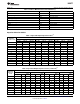
Step 4: Using Table 6 (fixed output voltage) or Table 10 (adjustable output voltage), determine the output
capacitance required for stable operation. Table 3 provides the specific capacitor type from the manufacturer of
choice.
Step 5: Determine an input capacitor from Table 7 for fixed output voltage applications. Use Table 3 to find the
specific capacitor type. For adjustable output circuits select a capacitor from Table 3 with a sufficient working
voltage (WV) rating greater than Vin max, and an rms current rating greater than one-half the maximum load
current (2 or more capacitors in parallel may be required).
Step 6: Select a diode from Table 8. The current rating of the diode must be greater than I load max and the
Reverse Voltage rating must be greater than Vin max.
Step 7: Include a 0.01μF/50V capacitor for Cboost in the design.
FIXED OUTPUT VOLTAGE DESIGN EXAMPLE
A system logic power supply bus of 3.3V is to be generated from a wall adapter which provides an unregulated
DC voltage of 13V to 16V. The maximum load current is 2.5A. Through-hole components are preferred.
14 Submit Documentation Feedback Copyright © 2004–2012, Texas Instruments Incorporated
Product Folder Links: LM2677