
Datasheet


High PFM Threshold
~1.016*Vout
Low1 PFM Threshold
~1.008*Vout
PFM Mode at Light Load
PWM Mode at Moderate to
Heavy Loads
PFET on
until
I
PFM
limit
reached
NFET on
drains
conductor
current
until
I inductor = 0
High PFM
Voltage
Threshold
reached,
go into
sleep mode
Low PFM
Threshold,
turn on
PFET
Current load
increases,
draws V
OUT
towards
Low2 PFM
Threshold
Low2 PFM Threshold,
switch back to PWM mode
Load current
increases
Low2 PFM Threshold
Vout
Z-Axis
Z-
Axis
Z
-
Axis
Z
-
Axis
Z
-
Ax
is
-18
V
IN
80:
I
PFM
= 66 mA
+
V
IN
160:
I
MODE
< 66 mA
)
(Typically +
LM26480
www.ti.com
SNVS543I –JANUARY 2008–REVISED MAY 2013
(3)
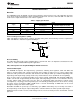
During PFM operation, the converter positions the output voltage slightly higher than the nominal output voltage
during PWM operation, allowing additional headroom for voltage drop during a load transient from light to heavy
load. The PFM comparators sense the output voltage via the feedback pin and control the switching of the output
FETs such that the output voltage ramps between 0.8% and 1.6% (typical) above the nominal PWM output
voltage. If the output voltage is below the ‘high’ PFM comparator threshold, the PMOS power switch is turned on.
It remains on until the output voltage exceeds the ‘high’ PFM threshold or the peak current exceeds the I
PFM
level
set for PFM mode. The typical peak current in PFM mode is:
(4)
Once the PMOS power switch is turned off, the NMOS power switch is turned on until the inductor current ramps
to zero. When the NMOS zero-current condition is detected, the NMOS power switch is turned off. If the output
voltage is below the ‘high’ PFM comparator threshold (see Figure 27), the PMOS switch is again turned on and
the cycle is repeated until the output reaches the desired level. Once the output reaches the ‘high’ PFM
threshold, the NMOS switch is turned on briefly to ramp the inductor current to zero and then both output
switches are turned off and the part enters an extremely low power mode. Quiescent supply current during this
‘sleep’ mode is less than 30 µA, which allows the part to achieve high efficiencies under extremely light load
conditions. When the output drops below the ‘low’ PFM threshold, the cycle repeats to restore the output voltage
to ~1.6% above the nominal PWM output voltage.
If the load current should increase during PFM mode (see Figure 27) causing the output voltage to fall below the
‘low2’ PFM threshold, the part will automatically transition into fixed-frequency PWM mode.
SW1, SW2 Control
SW1 and SW2 are enabled/disabled through the external enable pins.
The Modulation mode PWM/PFM is by default automatic and depends on the load as described above in the
functional description. The modulation mode can be factory trimmed, forcing the buck to operate in PWM mode
regardless of the load condition.
Figure 27.
Copyright © 2008–2013, Texas Instruments Incorporated Submit Documentation Feedback 17
Product Folder Links: LM26480