
Datasheet


(Vin ± Vout) x Vout
fsw x L x Vin
Iripple =
+
+
FB
COMP
SS
SYNC
EN
PGOOD
AVIN
4
5
8
6
9
14
7
VIN
3
VIN
VIN
SW
SW
BOOT
VDD
VBIAS
FPWM
FREQ
13
17
15
12
16
18
19
SW
20
PGND
10
11
AGND
EP
21
VIN: 4V ± 38V
C10
100 PF
C9
6.8 PF
R7
0:
VDD
C2
100 nF
R4
200 k:
PGOOD
EN
SYNC
R6
10 k:
C3
22 nF
C4
220 pF
C5
4.7 nF
R2
33.2
k:
R1
56.2 k:
C11
**
R5
124 k:
C7
120 PF
C1
10 PF
VDD
C6
0.1 PF
D1
5A
L1
VOUT: 3.3V/3A
15 PH
R3
12.1 k:
GND
C8
10 PF
1
2
** optional component
R2 =
Vout
Vfb
©
§
¹
·
R1
-1
LM26003
SNVS576D –AUGUST 2008–REVISED MARCH 2013
www.ti.com
PGOOD
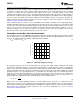
A power good pin, PGOOD, is available to monitor the output voltage status. The pin is internally connected to
an open drain MOSFET, which remains open while the output voltage is within operating range. PGOOD goes
low (low impedance to ground) when the output falls below 89% of nominal or EN is pulled low. When the output
voltage returns to within 95% of nominal, as measured at the FB pin, PGOOD returns to a high state. For
improved noise immunity, there is a 5 µs delay between the PGOOD threshold and the PGOOD pin going low.
Design Information
EXAMPLE CIRCUIT
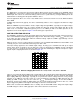
Figure 19 shows a complete typical application schematic. The components have been selected based on the
design criteria given in the following sections.
SETTING OUTPUT VOLTAGE
The output voltage is set by the ratio of a voltage divider at the FB pin as shown in the typical application. The
resistor values can be determined by the following equation:
(9)
Where Vfb = 1.236V typically.
A maximum value of 150 kΩ is recommended for the sum of R1 and R2.
As input voltage decreases towards the nominal output voltage, the LM26003 can skip up to seven off-pulses as
described in the LOW VIN OPERATION AND UVLO section. In low output voltage applications, if the on-time
reaches Ton
MIN
, the device will skip on-pulses to maintain regulation. There is no limit to the number of pulses
that are skipped. In this mode of operation, however, output ripple voltage may increase slightly.
Figure 19. Example Circuit 3A, 300 kHz
INDUCTOR
The output inductor should be selected based on inductor ripple current. The amount of inductor ripple current
compared to load current, or ripple content, is defined as Iripple/Iload. Ripple content should be less than 40%.
Inductor ripple current, Iripple, can be calculated as shown below:
(10)
Larger ripple content increases losses in the inductor and reduces the effective current limit.
14 Submit Documentation Feedback Copyright © 2008–2013, Texas Instruments Incorporated
Product Folder Links: LM26003