
Datasheet


Test Circuit and Layout Guidelines
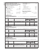
Fixed Output Voltage Versions
10133324
Component Values shown are for V
IN
= 15V,
V
OUT
= 5V, I
LOAD
= 2A.
C
IN
— 470 µF, 50V, Aluminum Electrolytic Nichicon “PM Series”
C
OUT
— 220 µF, 25V Aluminum Electrolytic, Nichicon “PM Series”
D1 — 3.3A, 60V Schottky Rectifier, 31DQ06 (International Rectifier)
L1 — 33 µH, See Inductor Selection Procedure
Adjustable Output Voltage Versions
10133325
Select R
1
to be approximately 1 kΩ, use a 1% resistor for best stability.
Component Values shown are for V
IN
= 20V,
V
OUT
= 10V, I
LOAD
= 2A.
C
IN
: — 470 µF, 35V, Aluminum Electrolytic Nichicon “PM Series”
C
OUT
: — 220 µF, 35V Aluminum Electrolytic, Nichicon “PM Series”
D1 — 3.3A, 60V Schottky Rectifier, 31DQ06 (International Rectifier)
L1 — 47 µH, See Inductor Selection Procedure
R
1
—1kΩ,1%
R
2
— 7.15k, 1%
C
FF
— 3.3 nF
Typical Values
C
SS
— 0.1 µF
C
DELAY
— 0.1 µF
R
PULL UP
— 4.7k (use 22k if V
OUT
is ≥ 45V)
†
Resistive divider is required to aviod exceeding maximum rating of 45V/3mA on/into flag pin.
††
Small signal Schottky diode to prevent damage to feedback pin by negative spike when output is shorted (C
FF
not being able to discharge immediately will
drag feedback pin below ground). Required if V
IN
>
40V
FIGURE 1. Standard Test Circuits and Layout Guides
LM2593HV
www.national.com 8