
Datasheet


LM2591HV
SNVS074D –MAY 2001–REVISED APRIL 2013
www.ti.com
(Adjustable Output Voltage Version)
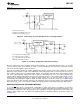
Figure 34. Inverting Regulator Ground Referenced Shutdown
Figure 35. Inverting Regulator Ground Referenced Shutdown using Opto Device
LAYOUT SUGGESTIONS
As in any switching regulator, layout is very important. Rapidly switching currents associated with wiring
inductance can generate voltage transients which can cause problems. For minimal inductance and ground
loops, with reference to Test Circuit and Layout Guidelines, the wires indicated by heavy lines should be wide
printed circuit traces and should be kept as short as possible. For best results, external components should
be located as close to the switcher lC as possible using ground plane construction or single point grounding.
If open core inductors are used, special care must be taken as to the location and positioning of this type of
inductor. Allowing the inductor flux to intersect sensitive feedback, lC groundpath and C
OUT
wiring can cause
problems.
When using the adjustable version, special care must be taken as to the location of the feedback resistors and
the associated wiring. Physically locate both resistors near the IC, and route the wiring away from the inductor,
especially an open core type of inductor.
20 Submit Documentation Feedback Copyright © 2001–2013, Texas Instruments Incorporated
Product Folder Links: LM2591HV