
Datasheet


LM1577, LM2577
SNOS658D –JUNE 1999–REVISED APRIL 2013
www.ti.com
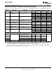
Electrical Characteristics—LM1577-12, LM2577-12 (continued)
Specifications with standard type face are for T
J
= 25°C, and those in bold type face apply over full Operating Temperature
Range. Unless otherwise specified, V
IN
= 5V, and I
SWITCH
= 0.
Symbol Parameter Conditions Typical LM1577-12 LM2577-12 Units
Limit
(1)(2)
Limit
(3)
(Limits)
V
UV
Input Supply I
SWITCH
= 100 mA 2.90 V
Undervoltage Lockout
2.70/2.65 2.70/2.65 V(min)
3.10/3.15 3.10/3.15 V(max)
f
O
Oscillator Frequency Measured at Switch Pin 52 kHz
I
SWITCH
= 100 mA
48/42 48/42 kHz(min)
56/62 56/62 kHz(max)
V
REF
Output Reference Measured at Feedback Pin V
Voltage V
IN
= 3.5V to 40V
12 11.76/11.64 11.76/11.64 V(min)
V
COMP
= 1.0V
12.24/12.36 12.24/12.36 V(max)
Output Reference V
IN
= 3.5V to 40V 7 mV
Voltage Line Regulator
R
FB
Feedback Pin Input 9.7 kΩ
Resistance
G
M
Error Amp I
COMP
= −30 μA to +30 μA 370 μmho
Transconductance V
COMP
= 1.0V
225/145 225/145 μmho(min)
515/615 515/615 μmho(max)
A
VOL
Error Amp V
COMP
= 1.1V to 1.9V 80 V/V
Voltage Gain R
COMP
= 1.0 MΩ
(5)
50/25 50/25 V/V(min)
Error Amplifier Upper Limit 2.4 V
Output Swing V
FEEDBACK
= 10.0V
2.2/2.0 2.2/2.0 V(min)
Lower Limit 0.3 V
V
FEEDBACK
= 15.0V
0.40/0.55 0.40/0.55 V(max)
Error Amplifier V
FEEDBACK
= 10.0V to 15.0V ±200 μA
Output Current V
COMP
= 1.0V
±130/±90 ±130/±90 μA(min)
±300/±400 ±300/±400 μA(max)
I
SS
Soft Start Current V
FEEDBACK
= 10.0V 5.0 μA
V
COMP
= 0V
2.5/1.5 2.5/1.5 μA(min)
7.5/9.5 7.5/9.5 μA(max)
D Maximum Duty Cycle V
COMP
= 1.5V 95 %
I
SWITCH
= 100 mA
93/90 93/90 %(min)
Switch 12.5 A/V
Transconductance
I
L
Switch Leakage V
SWITCH
= 65V 10 μA
Current V
FEEDBACK
= 15V (Switch Off)
300/600 300/600 μA(max)
V
SAT
Switch Saturation I
SWITCH
= 2.0A 0.5 V
Voltage V
COMP
= 2.0V (Max Duty Cycle)
0.7/0.9 0.7/0.9 V(max)
NPN Switch 4.5 A
Current Limit
3.7/3.0 3.7/3.0 A(min)
5.3/6.0 5.3/6.0 A(max)
(5) A 1.0 MΩ resistor is connected to the compensation pin (which is the error amplifier's output) to ensure accuracy in measuring A
VOL
. In
actual applications, this pin's load resistance should be ≥10 MΩ, resulting in A
VOL
that is typically twice the ensured minimum limit.
4 Submit Documentation Feedback Copyright © 1999–2013, Texas Instruments Incorporated
Product Folder Links: LM1577 LM2577