
Datasheet


LM2574, LM2574HV
www.ti.com
SNVS104C –JUNE 1999–REVISED APRIL 2013
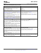
LM2574 Series Buck Regulator Design Procedure
PROCEDURE (Fixed Output Voltage Versions) EXAMPLE (Fixed Output Voltage Versions)
Given: Given:
V
OUT
= Regulated Output Voltage (3.3V, 5V, 12V, or 15V) V
OUT
= 5V
V
IN
(Max) = Maximum Input Voltage V
IN
(Max) = 15V
I
LOAD
(Max) = Maximum Load Current I
LOAD
(Max) = 0.4A
1. Inductor Selection (L1) 1. Inductor Selection (L1)
A. Select the correct Inductor value selection guide from Figure 25, A. Use the selection guide shown in Figure 26.
Figure 26, Figure 27, or Figure 28. (Output voltages of 3.3V, 5V, 12V
B. From the selection guide, the inductance area intersected by the
or 15V respectively). For other output voltages, see the design
15V line and 0.4A line is 330.
procedure for the adjustable version.
C. Inductor value required is 330 μH. From Table 1, choose Pulse
B. From the inductor value selection guide, identify the inductance
Engineering PE-52627, Renco RL-1284-330, or NPI NP5920/5921.
region intersected by V
IN
(Max) and I
LOAD
(Max).
C. Select an appropriate inductor from Table 1. Part numbers are
listed for three inductor manufacturers. The inductor chosen must be
rated for operation at the LM2574 switching frequency (52 kHz) and
for a current rating of 1.5 × I
LOAD
. For additional inductor information,
see INDUCTOR SELECTION in Application Hints of this data sheet.
2. Output Capacitor Selection (C
OUT
) 2. Output Capacitor Selection (C
OUT
)
A. The value of the output capacitor together with the inductor A. C
OUT
= 100 μF to 470 μF standard aluminum electrolytic.
defines the dominate pole-pair of the switching regulator loop. For
B. Capacitor voltage rating = 20V.
stable operation and an acceptable output ripple voltage,
(approximately 1% of the output voltage) a value between 100 μF
and 470 μF is recommended.
B. The capacitor's voltage rating should be at least 1.5 times greater
than the output voltage. For a 5V regulator, a rating of at least 8V is
appropriate, and a 10V or 15V rating is recommended.
Higher voltage electrolytic capacitors generally have lower ESR
numbers, and for this reason it may be necessary to select a
capacitor rated for a higher voltage than would normally be needed.
3. Catch Diode Selection (D1) 3. Catch Diode Selection (D1)
A. The catch-diode current rating must be at least 1.5 times greater A. For this example, a 1A current rating is adequate.
than the maximum load current. Also, if the power supply design
B. Use a 20V 1N5817 or SR102 Schottky diode, or any of the
must withstand a continuous output short, the diode should have a
suggested fast-recovery diodes shown in Table 2.
current rating equal to the maximum current limit of the LM2574. The
most stressful condition for this diode is an overload or shorted
output condition.
B. The reverse voltage rating of the diode should be at least 1.25
times the maximum input voltage.
4. Input Capacitor (C
IN
) 4. Input Capacitor (C
IN
)
An aluminum or tantalum electrolytic bypass capacitor located close A 22 μF aluminum electrolytic capacitor located near the input and
to the regulator is needed for stable operation. ground pins provides sufficient bypassing.
Copyright © 1999–2013, Texas Instruments Incorporated Submit Documentation Feedback 13
Product Folder Links: LM2574 LM2574HV