
Datasheet


LM2574, LM2574HV
www.ti.com
SNVS104C –JUNE 1999–REVISED APRIL 2013
UNDERVOLTAGE LOCKOUT
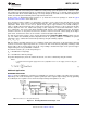
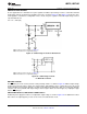
In some applications it is desirable to keep the regulator off until the input voltage reaches a certain threshold. An
undervoltage lockout circuit which accomplishes this task is shown in Figure 33 while Figure 34 shows the same
circuit applied to a buck-boost configuration. These circuits keep the regulator off until the input voltage reaches
a predetermined level.
V
TH
≈ V
Z1
+ 2V
BE
(Q1)
Note: Complete circuit not shown (see Figure 31).
Note: Pin numbers are for 8-pin PDIP package.
Figure 33. Undervoltage Lockout for Buck Circuit
Note: Complete circuit not shown (see Figure 31 ).
Note: Pin numbers are for 8-pin PDIP package.
Figure 34. Undervoltage Lockout
for Buck-Boost Circuit
DELAYED STARTUP
The ON /OFF pin can be used to provide a delayed startup feature as shown in Figure 35. With an input voltage
of 20V and for the part values shown, the circuit provides approximately 10 ms of delay time before the circuit
begins switching. Increasing the RC time constant can provide longer delay times. But excessively large RC time
constants can cause problems with input voltages that are high in 60 Hz or 120 Hz ripple, by coupling the ripple
into the ON /OFF pin.
ADJUSTABLE OUTPUT, LOW-RIPPLE POWER SUPPLY
A 500 mA power supply that features an adjustable output voltage is shown in Figure 36. An additional L-C filter
that reduces the output ripple by a factor of 10 or more is included in this circuit.
Copyright © 1999–2013, Texas Instruments Incorporated Submit Documentation Feedback 23
Product Folder Links: LM2574 LM2574HV